Other Parts Discussed in Thread: PGA460, PGA460-Q1, USB2ANY, MSP-EXP430F5529LP, ENERGIA, , MSP430F5229
PGA460 Frequently Asked Questions (FAQ) & EVM Troubleshooting Guide
www.ti.com/.../technicaldocuments
Last updated: 03/08/2017
Version: 1.0.0
Author: A. Whitehead
This document is intended to answer the most common and frequently asked questions (FAQ) users have when evaluating the PGA460 or PGA460-Q1 EVM and GUI. Step-by-step procedures to hardware troubleshooting and software debugging are provided. Recommendations to improve performance and best practices to prevent device failure, GUI errors, or improper measurement techniques are also discussed.
1. Overview
This document divides the FAQ into categories based on getting started, hardware installation and setup, software installation and setup, hardware modifications, running the software, running the hardware, and environmental factors. If your question is not listed in this document, post your question to the ultrasonic sensing forum on e2e.ti.com. This document will be maintained and updated regularly.
2. Getting Started and Evaluation Flow
2.1. Where do I begin?
To begin evaluation of the PGA460, purchase the PGA460-Q1 EVM, which contains all the necessary hardware required to evaluate a full-scale ultrasonic module equivalent with a master controller. Once the hardware is in hand, download and view the PGA460-Q1 EVM Quick Start Guide. The quick start guide provides the step-by-step procedure to setting up the EVM hardware and installing the PGA460-Q1 EVM GUI. In addition to the supporting documentation, the six part PGA460 EVM & GUI Video Series demonstrates how to setup, install, and run the evaluation tools. The basic device settings are introduced to start capturing return echoes within minutes of unboxing the EVM. For a detailed description of the EVM’s hardware and GUI, refer to the PGA460-Q1 Ultrasonic Signal Conditioner EVM with Transducer User's Guide.
2.2. After setting up the EVM, and verifying the GUI works, how do I tune my solution?
To tune an ultrasonic sensor solution, the user must understand the capabilities and limitations of the ultrasonic components. The PGA460-Q1 Ultrasonic Module Hardware and Software Optimization application note introduces a detailed description on how to determine which transducer, driver, and power combination should be used depending on the targeted objects and environmental operating conditions. Throughout your evaluation and component selection, refer to the PGA460-Q1 Frequently Asked Questions (FAQ) and EVM Troubleshooting Guide application note for advanced troubleshooting and debugging.
2.3. After tuning my solution on the EVM, how do I port the settings from the GUI and configure my custom solution?
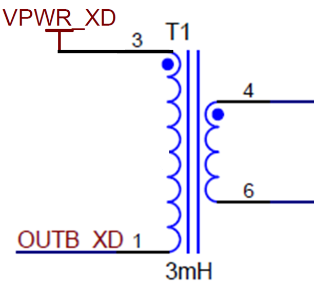
The first step to porting your solution is to capture the optimized register map using the GUI. The GUI is able to save all user EEPROM settings, as well as the threshold times and levels stored in volatile memory. To save the register map using the GUI, navigate to the Memory Map tab. Before clicking the Save Grid icon, be sure to click the Read All icon to update the memory map page with the latest device settings. When the Save Grid icon is clicked, the user will be prompted to save the time stamped register map grid as a .txt file. This .txt file can be used as a reference or be loaded to other PGA460 devices using the GUI.
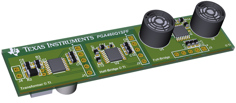
Since the EVM is not the optimal size for an ultrasonic module, the PGA460Q1SFF reference design (to be released) is available as example to the small form factor (SFF) size for a PGA460 solution, and offers three variants. The variants include a transformer driven twisted-pair closed-top transducer, a half-bridge driven surface mount open-top transducer, and a full-bridge driven radial lead bi-static pair on this three-in-one reference design. Depending on the transducer and driver mode optimized on the EVM, select the appropriate reference design variant as a starting point for your customized hardware.
The SFF reference design routes the UART’s TXD and RXD pins and the IO pin to the five-pin connector on each variant. Typically either only the two UART pins or the single IO pin are routed the module connector for communication. Power and ground are always required, so the minimum number of pins per module is three.
Figure 1. PGA460Q1SFF Rendering
For a comparison of typical use-case results when using the SFF variants, refer to the PGA460 Configurations and Test Results application note (to be released). This application note includes minimum and maximum ranging performance the SFF variants can achieve for various types of targets. The register map settings for each configuration will be included as a starting point and reference for your testing.
The GUI primarily uses UART to evaluate the PGA460. However, TCI and One-Wire UART can also be used to fully program and evaluate the PGA460. The GUI uses TI’s USB2ANY proprietary code to communicate from a PC to the PGA460 device. The GUI source code is not available to the public. Instead, the PGA460 Energia Library and Code Example and PGA460-Q1 Software Development Guide should be used as an example for master controller implementation and programming guidelines. The example runs on the Energia IDE when using any of the TI LaunchPad development kits, including the MSP-EXP430F5529LP base of the PGA460-Q1 EVM. Therefore, the PGA460-Q1 EVM can be used to run the GUI or Energia sketches. Modify the Energia sketch to meet the system requirements of the end solution.
2.4. How can I prepare for mass production programming and system integration?
If the system requires the PGA460 device’s user EEPROM settings to be burned prior to the ultrasonic module to being installed in the system, then a custom mass production tool must be designed to program the EEPROM module. The MSP-EXP430F5529LP from the PGA460-Q1 EVM can be used as the base of the mass production tool, and would only require the user to build a mass production BoosterPack for the custom PGA460 module form factor. The PGA460 Energia sketch can be modified such that the mass production tool performs a bulk EEPROM write and burn to multiple modules simultaneously or sequentially based on the PGA460 address assigned to each module. For instance, if all modules will have the same UART address for a star topology system (independent UART channel for each module from the master), then all modules can be programmed simultaneously. If each module requires a different UART address for a bus topology system (a single UART channel shared between each module), then the modules must be written to sequentially. The PGA460 UART address is ‘0’ by factory-default.
If the master controller within the system is able to perform the bulk EEPROM write and burn command, then a mass production tool is not necessary, and a blank module can be installed in the system. This approach is only recommended for a star topology because the PGA460 is not able to perform daisy-chain or automatic slave node position detection (SNPD). If a bus topology is required, then the modules must be pre-programmed, installed and programmed one at a time in the system, or use a the support of external switches and master control signals to achieve SNPD. See section 4.14 for an example implementation of SNPD on for PGA460 bus.
3. Hardware Installation and Setup
3.1. How should I position the shunt on the “Alt Pwr Modes” jumper block?
The shunt is not required to operate the EVM. The shunt is recommended for quick out-of-box evaluation of the PGA460-Q1 EVM when installed in the “LP-USB” mode, and using only a computer or laptop to power and communicate with the EVM. However, the boost-circuit to power the PGA460 will limit the long range performance of the transformer driven mode. For a more robust form of evaluation, completely remove the shunt (or save the shunt across the jumper block’s pins 2-4), and power the BOOSTXL-PGA460 using an external supply at the barrel connector or three pin connector socket. The “X-EXT” mode should not be used for initial evaluation. Refer to the PGA460-Q1 Ultrasonic Signal Conditioner EVM with Transducer User's Guide for details on the different power modes and shunt positions.
3.2. Why is my EVM consuming 70mA, or more than the average static current of 13mA?
If your EVM is consuming 70mA, then you have shunt shorted the “X-EXT” (exclusively external) on the Alt Pwr Modes jumper block, connected an external supply, and have connected the MSP-EXP430F5529LP to the PC using USB. In X-EXT mode, the USB cannot be connected, and should typically consume 35mA if correctly operating in X-EXT mode. If the USB is connected, then both the USB port and on-board buck circuit are attempting to power the MSP-EXP430F5529LP and BOOSTXL-PGA460 simultaneously. The USB should only be connected when in standard (no shunt) or “LP-USB” power mode. The BOOSTXL-PGA460 motherboard should not exceed 13mA of current consumption when in inactive or listen-only mode. Ensure that no other BoosterPack or load is connected to the external supply. Expect transient currents up to 500mA during the bursting sequence.
3.3. Can I use any LaunchPad with the BOOSTXL-PGA460?
The 40-pin BOOSTXL-PGA460 motherboard is compatible with the majority of LaunchPad development kits, including the 20-pin variants. The necessary pins to communicate through UART, TCI, and One-Wire UART modes and the GPIO controls for settings the state of the communication switch are all accessible from the 20-pin, 40-pin, and 80-pin standards. Synchronous mode is only enabled for some of the 40-pin and 80-pin options. The PGA460-Q1 EVM GUI firmware will only load onto the MSP-EXP430F5529LP.
Figure 2. BOOSTXL-PGA460 BoosterPack Pinout
3.4. The closed-top twisted pair transducer hangs from the daughtercard, and tends to points down. How do you recommend I mount the transducer with a support or stand?
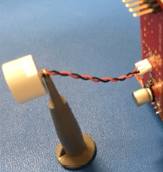
Initially, use the packaging sponge from the box the BOOSTXL-PGA460 was shipped in as mounting material for the twisted pair transducer. Cut out a 5cm x 5cm square of sponge, and puncture the center with a pen sized hole. Lodge the transducer in the hole of the sponge. The soft sponge like material is ideal because it will not load or dampen the vibrating mechanics of the transducer shell. The transducer should not be fastened with a metallic vice or clamp, taped to the table, nor held by the user’s fingers, as this will reduce performance. The fewer materials making contact with the transducer shell, the better the performance. Fastening the twisted cables, with minor contact to the rear of the transducer is an alternative to securing the shell. For module sized solutions, a rubber gasket is typically used to hold and seal the module in place, and to isolate the circuit from the outward facing transducer.
Figure 3. Transducer mounting options
3.5. Is a transducer’s pin polarity important?
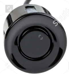
Some transducers have a pin polarity marker, while others are reversible (non-polar). Typically, closed-top transducers have polarity due to the conductive shell connecting to the negative terminal. Grounding the negative terminal is crucial for ESD robustness when the shell of the transducer is the discharge point for the ESD source. The ultrasonic returns at the positive terminal are superior to the returns seen at the negative terminal, since the shell is more likely to pick-up environmental noise. The majority of open-top transducers are non-polar due to their plastic, non-conductive, or floating shells, though some, such as the Murata MA40H1S-R, do have conductive shells shared with the negative terminal. Be sure to read the transducer’s datasheet to determine if polarity must be considered.
Figure 4. Transducer pin polarity examples
3.6. Is a transducer’s face orientation important?
Some transducers have varying degrees of coverage in different axes. For instance, the Murata MA58MF14-7N has a wide field of view (FOV) in the horizontal axis, but a narrow FOV in the vertical axes. Meanwhile, the Murata MA40H1S-R is has the same omni-directional FOV in the x-, y-, and z-axis. To determine the face orientation, typically a mechanical or visual marker is provided. The Murata MA58MF14-7N should be oriented such that the white epoxy slotted backing and rear cutouts stand upright.
Figure 5. Beam pattern of MA58MF14-7N in horizontal and vertical axes
4. Software Installation and Setup
4.1. During installation, I was not prompted to install the MSP430 and Code Composer Studio (CSS) drivers mentioned in the Quick Start video. Are these driver files important?
The driver files are required to load the “boostxlpga460-firmware.bat” batch file onto the MSP-EXP430F5529LP for GUI compatibility. These drivers include “USB_CDC”, “USB_FET_Win7_8_10_64”, and “USB_eZ-RF”, and will only install on a 64-bit version of Windows 7 or newer. Before reading the remainder of this answer, try loading the batch file using the PGA460-Q1 EVM GUI. If you are able to successfully load the batch file, then the drivers were installed without prompts, or the PC had previously installed the same driver files. If Code Composer Studio was already installed on the PC prior to the PGA460-Q1 EVM GUI install, the required driver files were likely already installed.
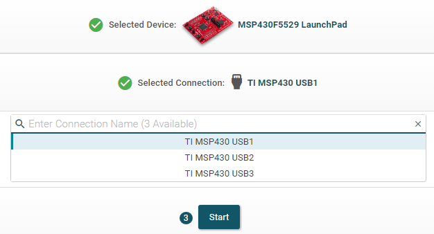
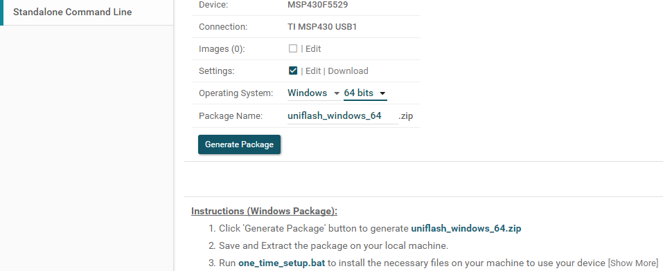
To manually install the necessary drivers, navigate to the install-created directory of “DocumentsàBOOSTXL-PGA460” or “My DocumentsàBOOSTXL-PGA460”, and run the “one_time_setup.bat”. If you do not have this file on your PC, the GUI and the associated files did not install properly. Re-install the GUI onto your machine if you do not have this file. Be sure that the one_time_batch.bat file is located and run from the same directly as the “dpinst_64_eng.exe”, “ccs_base” folder, and “user_files” folder. To independently install the drivers, visit https://dev.ti.com/uniflash, and create a TI account if you don’t already have one. Create a new session using the MSP430F5229 LaunchPad at the first available connection name (i.e., TI MSP430 USB1).
Navigate to the Standalone Command Line tab, ensure the 64 bit operating system option is selected, and click generate package. Follow the instructions up to the one_time_setup.bat executable.
If you require a 32-bit version of the driver installer, follow the same steps. Contact TI support through the E2E forum for the 32-bit version of the “boostxlpga460-firmware.bat” file. Successful installation of the drivers may require administrative privileges.
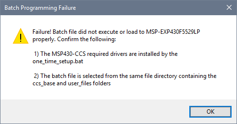
4.2. The “boostxlpga460-firmware.bat” batch file fails to install.
Figure 6. Batch Programming Failure prompt
If the batch file fails to install, ensure the MSP430 and Code Composer Studio (CCS) driver files successfully installed during the PGA460-Q1 EVM GUI install wizard or when manually installed by the “one_time_setup.bat” file. Refer to question 4.1 for additional details on the driver file installation. The “boostxlpga460-firmware.bat” must be loaded from the same directory containing the “ccs_base” and “user_files” installed during the PGA460-Q1 EVM GUI wizard. All aforementioned files and folders will be stored in the install-created folder at “DocumentsàBOOSTXL-PGA460” or “My DocumentsàBOOSTXL-PGA460”.
The batch file must only be flash programmed onto the MSP-EXP430F5529LP once during initial setup. Unless the LaunchPad is repurposed or programmed for a purpose other the PGA460-Q1 EVM GUI evaluation, the user will not have to repeat the batch file upload.
4.3. I cannot open the GUI. A Windows dialog box immediately opens stating, “PGA460Q1EVM GUI has stopped working”.
Figure 7. PGA460Q1EVM GUI open error
This problem is typically a result of the GUI executable being run outside of the installation directory. The “PGA460Q1EVM-x.x.x.x.exe” must be run from the same folder containing the “USB2ANY.dll” and “Microsoft.VisualBasic.PowerPacks.Vs.dll”. These DLL files are installed in the same path as the executable when using the PGA460-Q1 EVM GUI install wizard. The GUI depends on these two DLL files to initialize and function properly.
Hardware Modifications
4.4. How do I use a different transducer on the transformer driven circuit?
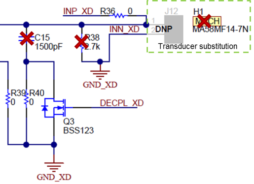
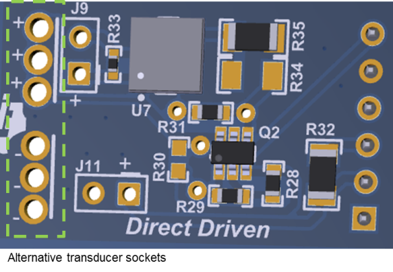
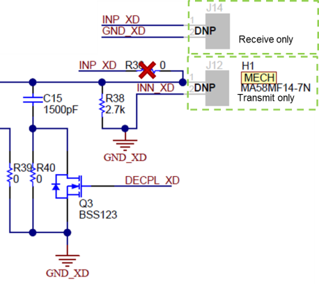
To use a different transducer on the transformer driven circuit, desolder the Murata MA58MF14-7N from the J12 socket. TI also recommends that the tuning capacitor of 1500pF at C15 and damping resistor of 2.7kΩ at R38 be desoldered to enable the transducer to resonate freely and without being unintentionally detuned. The new transducer can be populated at J12, or across the alternative transducer socket’s positively and negatively marked terminals on the transformer driven half of the daughtercard. If a tuning capacitor and damping resistor are required for the new transducer, refer to the PGA460-Q1 Ultrasonic Module Hardware and Software Optimization application note for guidance.
Figure 8. Transformer Driven Transducer Substitution
4.5. How do I use a different transducer on the direct driven circuit?
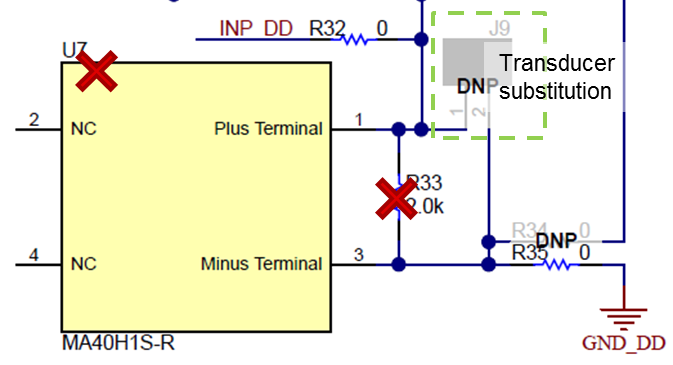
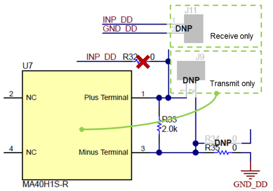
To use a different transducer on the direct driven circuit, desolder the Murata MA40H1S-R from the U7 pads. TI also recommends that the damping resistor of 2.0kΩ be desoldered to enable the transducer to resonate freely. The new transducer can be populated at J9, or across the alternative transducer socket’s positively and negatively marked terminals on the direct driven half of the daughtercard. If a damping resistor is required for the new transducer, refer to the PGA460-Q1 Ultrasonic Module Hardware and Software Optimization application note for guidance. Tuning capacitors are not required for direct-driven transducers.
Figure 9. Direct Driven Transducer Substitution
4.6. Can I drive a closed-top transducer on the direct driven circuit?
Yes, closed-top transducers can be paired with the direct driven circuit. However, the direct driven circuit will not be able to effectively drive the majority of closed top transducers at maximum transmitting capacity. The direct driven circuit is limited to 60Vpp in full-bridge mode since the PGA460’s OUTA and OUTB pins are rated for an absolute maximum of 30V. The overall loss in driver strengths yields a shorter detectable range.
4.7. Can I drive an open-top transducer on the transformer driven circuit?
Using the transformer driven circuit is not recommended for open-top transducers, unless the reference voltage or center-tap voltage of the transducer is supplied with a very small voltage. The majority of center-tap transformers have an average turns-ratio of 1:1:10. For instance, to drive an open-top transducer rated for 20Vpp, the center-tap voltage reference must be 1V. Supplying the center-tap with the minimum PGA460 supply voltage of 6V will theoretically yield a transducer driving voltage of 120Vpp, which is beyond the typical rating of most open-top transducers. Driving any transducer beyond the specified limit will damage the transducer’s piezoelectric membrane.
4.8. How do I enable the daughtercard to use a bi-static transducer pair (a separate transmitter and receiver)?
For the transformer driven mode, desolder the 0Ω resistor at R36. This disconnects the return path typically shared with the transmitter’s positive terminal. Connect the receive-only transducer to the J14 socket.
For the direct driven mode, desolder the 0Ω resistor at R32. This disconnects the return path typically shared with the transmitter’s positive terminal. Connect the receive-only transducer to the J11 socket.
|
Transformer Mode |
Direct Mode |
Figure 10. Enabling Bi-Static Mode on Daughtercard
4.9. How do I enable the daughtercard to use full-bridge direct drive in bi-static mode?
Full-bridge is only available for the bi-static mode, and can be enabled by making the following hardware changes:
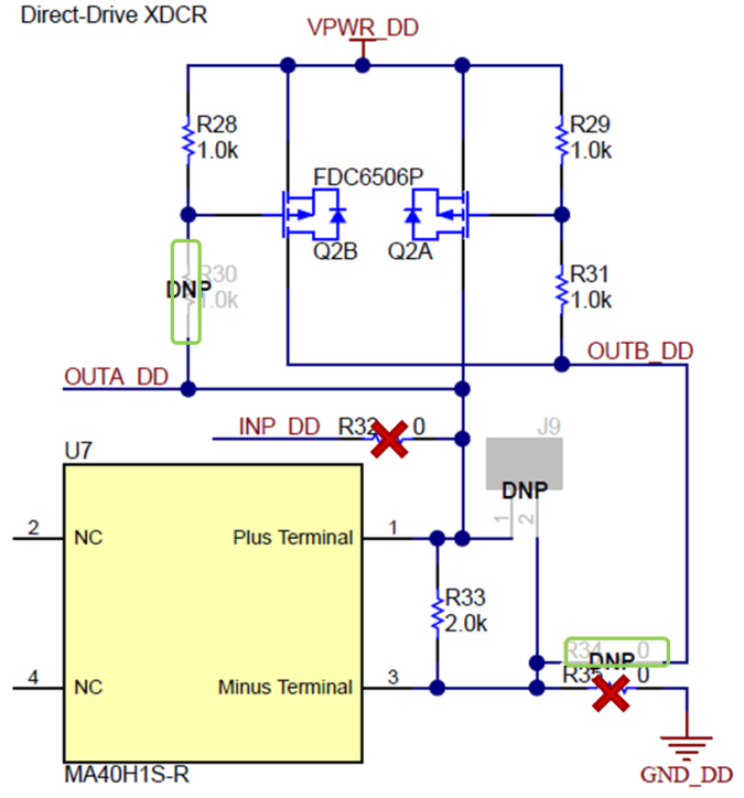
- Desolder the 0Ω resistor at R32. This disconnects the return path typically shared with the transmitter’s positive terminal. Connect the receive-only transducer to the J11 socket.
- Desolder the 0Ω resistor at R35, and use the same 0Ω resistor to populate resistor R34.
- Populate the 1kΩ resistor at R30.
Figure 11. Full-bridge bi-static mode modifications
4.10.How do I enable the daughtercard to use a full-bridge direct drive in mono-static mode?
Full-bridge direct driven mode only supports the bi-static mode due to the driving architecture of the PGA460. Mono-static can be supported by the transformer driven or half-bridge driven. If full-bridge mono-static mode is required, contact TI support through the E2E forum, and mention this FAQ.
4.11.Can my supply voltage be different from the driver’s voltage reference?
Yes, the PGA460 can be supplied with a smaller or larger voltage versus the voltage sinking through the OUTA and OUTB pins. For example, the PGA460’s VPWR pin can be supplied with the minimum of 6V, while the transformer’s center-tap or direct driver’s high-side reference is at 30V. Conversely, the PGA460’s VPWR pin can be supplied with the maximum of 28V, while the transformer’s center-tap or direct driver’s high-side reference is at 6V (or even lower). Note, the VPWR Overvoltage threshold can be set to a maximum of 28.3V; therefore, the PGA460 VPWR pin cannot be supplied with 30V, though the OUTA and OUTB pins can.
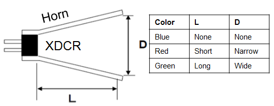
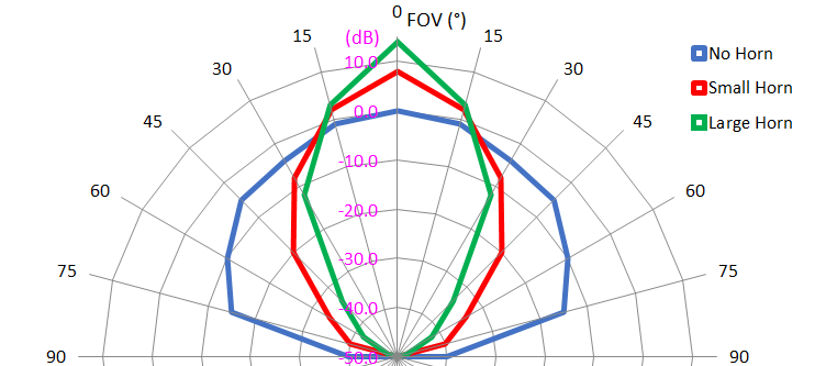
4.12.What effect does a transducer “horn” have on the beam pattern? How can I focus the ultrasonic energy into a more forward facing direction?
A horn is a mechanical add-on to the transducer, which artificially increases the depth and diameter of the transducer. By increasing the depth and diameter of the transducer, the beam angle is constrained to a narrower, more direct, and forward facing direction. By increasing the directivity of the beam, more sound pressure level is also transmitted in the forward facing direction, which improves the detectable range of the transducer. A horn is recommended to minimize the range of side-lobes and blind-spots, while enhancing the forward facing performance. Any transducer can be fitted with a horn for this purpose. A horn can only be use to focus, and cannot be used to widen the beam angle.
Figure 12. Horn to Focus Field-of-View
4.13.Can I use the IOREG or AVDD rails of the internal PGA460 regulators to power other components or microcontrollers?
The AVDD and IOREG regulators are not intended to support any external load. AVDD is very sensitive to load changes because it is used as a precision voltage reference, current bias, and internal clocking. IOREG is less sensitive, but still used to generate the supply voltage for the USART, DECPL, and TEST pins for digital functionality. Using the internal regulators to supply low power will be based on user discretion and testing.
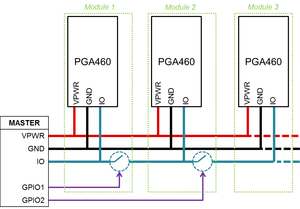
4.14.Is daisy-chain supported by the PGA460? Can the master controller automatically differentiate and program the PGA460 UART address?
Daisy-chain auto-addressing and automatic slave node position detection (SNPD) are not supported by the PGA460. External hardware or switches must be used in combination with the external master controller to automatically assign address to multiple PGA460 devices connected to the same bus. The example provided is interchangeable for the IO and TX pin. When switching IO, be sure select a bi-direction switch rated for VPWR (up to 30V). The TX pin is a unidirectional pin rated at either 3.3V (default) or 5.0V.
Figure 13. Master controlled auto-addressing example
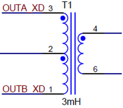
4.15.How do I use a single-ended transformer instead of a center-tap transformer?
To use a single-ended transformer to substitute a center-tap transformer, only the OUTA or OUTB pin must be used. The primary windings would be connected such that one end is connected to a constant supply rail (such as VPWR), and the other end is connected to OUTA or OUTB. If OUTA is used, then OUTB will be floating, or vice-versa.
Single-ended transformers are able to drive the transducer during half of the period, while the transducer’s resonance drives the remaining half of the period in the opposite direction. Therefore, single-ended transformers are slightly less effective in generating maximum sound pressure level when compared to center-tap transformers. A center-tap transformer can be used in single-ended mode to change (decrease) the turns-ratio.
Figure 14. Transformer Connections
5. Running the Software
5.1. How can I detect an object if it is further than 11m?
To detect an object further than 11m, the user must issue n-number of listen-only (LO) commands immediately after the initial burst-and-listen (BAL) command expires.
For example, if the target is at 15m, then the BAL command can be set with a maximum record length of 65ms (or 11.2m to target) using Preset 1 (P1). Since a difference of 3.8m must be accounted for after the BAL record length expires, Preset 2 (P2) must be set with a minimum record length of 25ms (or 4.214m to target). Once the Presets are set with the appropriate times, the master issues a P1 BAL command, waits until 65ms expire, then immediately issues a P2 LO command. When the Ultrasonic Measurement Results are pulled, an additional 11.2m must be added to the distance result to correctly capture the 15m object detection recording. The subsequent communication delay between the P1 BAL and P2 LO commands may or may not be negligible depending on the baud rate or communication mode used. Account for any master control delays in the distance calculation.
To detect beyond 22.4m, initially issue a P1 BAL command, followed by a P2 LO command, and another P2 LO command, where P2 is set with a record length of 11.2m. Ultrasonic measurements beyond 10m become difficult to capture, unless the target is a large, flat, reflective surface. For this reason, the PGA460 was set with the typical maximum limit of 11.2m for a BAL or LO single command.
5.2. How can I detect more than eight objects? Can I set the threshold to ignore ringing decay ripple or objects for a given time after bursting? How can the Threshold Offset be used?
The threshold map can be set to ignore ultrasonic activity at any point of the record window, when the threshold level is set to a value of 255. The user may want to consider setting the threshold to a value of 255 during the initial burst and decay time. Even when the return data is saturated, such as during the burst window or strong return peaks, the threshold comparator will not trigger when the threshold is maximized.
For threshold levels 1-8, the value of 255 can only be attained when the threshold level is maximized to a value of 248, and the threshold offset is set to a maximum positive value of +7. This offset applies to all 1-8 levels. For levels 9-12, the offset does not apply, and these levels can be independently set to 255.

Figure 15. Maximizing the threshold level to ignore ultrasonic activity
5.3. Can I automatically set the threshold map?
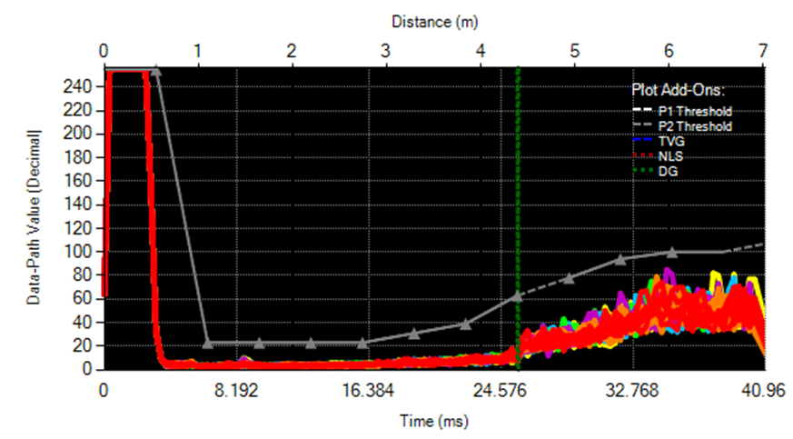
The PGA460 does not implement automatic threshold mapping, but the master controller can implement a function to set the threshold based on the average echo data dump of a no-object burst-and-listen (NOBAL) profile. Multiple iterations (such as 100) of the NOBAL command should be to run and recorded to collect a reliable running average of the noise floor. The threshold is then mapped such that the timing of all 12 thresholds points are spaced to fit just within or beyond the record time length of the respective preset. The levels would be set based on the worst case value of the segmentation between the level in question and the subsequent level. An additional margin of 8 or more decimal spaces should be added as buffer to the threshold levels.
Figure 16. Auto-mapped threshold after 100 NOBAL loops
5.4. Can I automatically set the time varying gain?
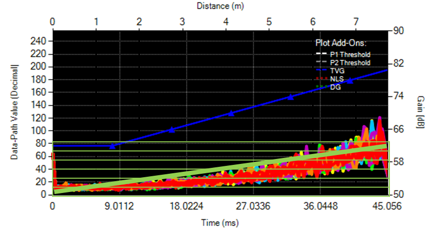
The PGA460 does not implement an automatic time varying gain configuration, but the master controller can implement a function to ramp the time varying gain profile as an automatic gain controller. For example, with the short and long range digital gain multipliers set to ‘x1’, the no-object listen-only (NOLO) command can be run for multiple iterations (such as 100) to collect the average noise floor value of the currently set fixed gain value. The gain could be ramped such the timing of all 6 TVG points are space to fix exactly within or beyond the record time length the respective preset. Since the time varying gain is shared between Preset 1 and Preset 2, the gain may need to be configured for the preset with the longest record time length, or configured to switch dynamically between each preset. The levels could be targeted to ramp the noise floor at a 5% rate between each level. For instance, the initial gain could set the noise floor to 5% of the 255 maximum, the first level set to 10%, the second level set to 15%, etc. The last level (fifth) would be set to 30% (or 77) of the 255 maximum. Repeating the sweep for the various digital gain multipliers will be necessary to leverage all of the gain controls offered by the PGA460.
Figure 17. Automatic linear fit of TVG after 100 NOLO loops
5.5. Can I evaluate multiple PGA460 devices using the same UART bus of the PGA460-Q1 EVM?
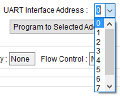
Yes, the GUI can be set to communicate with any PGA460 UART address, with a default UART address of ‘0’ out of ‘7’. To communicate to a non-0 UART address, navigate to the Interface Mode page, and select the UART Interface Address from the dropdown menu of the Command Selection box. To program the UART address to the selected address, click the Program to Selected Addr button underneath the dropdown. This does not burn the address to the EEPROM memory, and only writes to update the shadow register containing the UART address. To burn the new address to EEPROM, navigate to the Test Mode page, and click the Program EEPROM button. This will ensure that the UART address of the configured PGA460 is the newly programmed value.
Figure 18. UART Interface Address Dropdown
If an external PGA460 is connected to the BOOSTXL-PGA460 BoosterPack UART terminal, communication to the PGA460 installed on the BOOSTXL-PGA460 can be disabled by navigating to the window menu’s Edit tab, and clicking the Disable BOOSTXL-PGA460 Communication option. This allows communication commands to still transmit from the MSP-EXP430F5529LP, but prevents the master issued commands from reaching the on-board PGA460. This ensures that the external PGA460 device is exclusively contacted to prevent data collision, assuming both the on-board and external PGA460 devices shared the same UART address.
Figure 19. Disable communication to PGA460 on BOOSTXL-PGA460 motherboard
5.6. The ultrasonic measurement result data is random, very short, always the maximum value, or never updates.
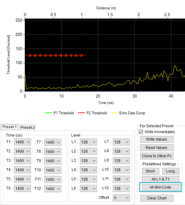
Before the ultrasonic measurement results can be of any use, the thresholds must be mapped for object detection based on the echo data dump profile. Use the mid-code threshold timing and levels option to bypass the need for manual threshold optimization. The mid-code option sets the threshold to a fixed 50% detection level.
Figure 20. Mid-code threshold times and levels
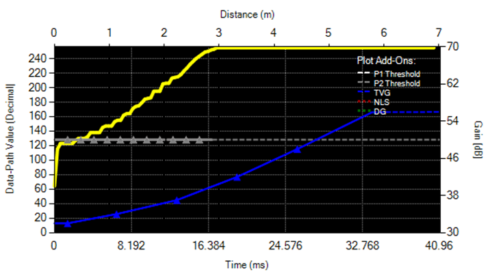
If the threshold has been set appropriately, and the value returned is always less than 1cm, then the threshold is initially set too high, but not maximized. At low analog gains, the DSP output supplied to the data comparator to detect a threshold crossing initially ramps during the burst and decay window. As a result, the echo data dump equivalent is not immediately saturated as it is represented in the analog domain, thus the threshold comparator can be false-triggered by the initially ramped DSP output. To prevent this false-trigger, initially set the threshold to the maximum value of 255, increase your threshold deglitch time, or lower the threshold such that ramping is at an initial value above the threshold level. Alternatively, set the initial gain to a larger value such that the ramping is saturated, and does not trigger the threshold.
Figure 21. DSP output ramp triggering a false positive
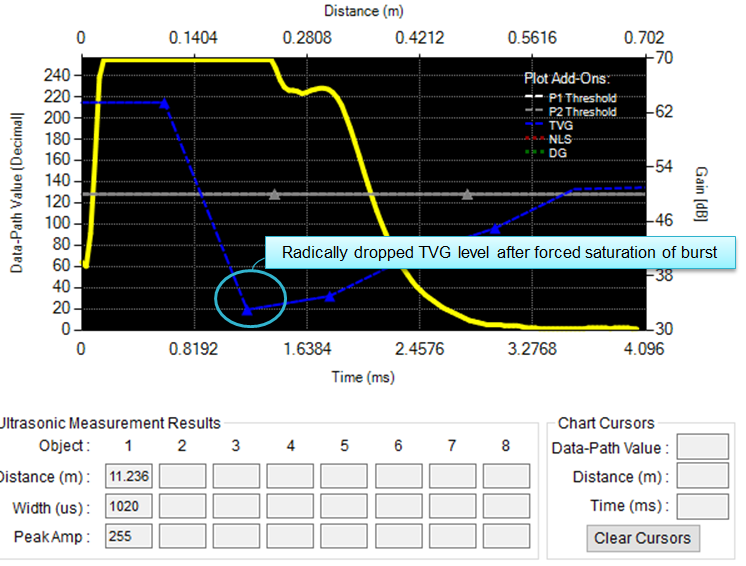
Best practice is to initialize the TVG and/or SR digital gain to a large value during the expecting burst and initial decay window, and radically reduce the TVG to a lower value during the later portion of the decay period to enable short range detection.
Figure 22. TVG max-to-min trough to saturate initial burst of echo data dump
If the threshold is always at a maximum value, the threshold is set too high throughout the entire profile, or no object is detected. Reduce the threshold levels to force the threshold comparator to trigger. A forced trigger will confirm whether a burst-and-listen command has truly executed.
If the ultrasonic measurement results (UMR) are not updated, ensure that the DATADUMP_EN bit of the EE_CNTRL register is disabled (default). If the DATADUMP_EN bit is enabled, the echo data dump memory is filled, and the UMR will not update since the threshold comparator disabled. Only the echo data dump memory can be filled, or the ultrasonic measurement results be captured, but not both simultaneously. When the GUI displays the echo data dump and captures the ultrasonic measurement results, two independent burst-and-listen commands are run sequentially.
5.7. The noise floor increases significantly at long distances.
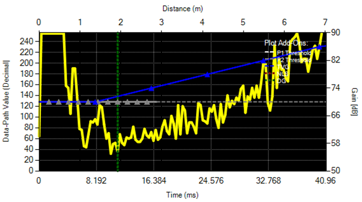
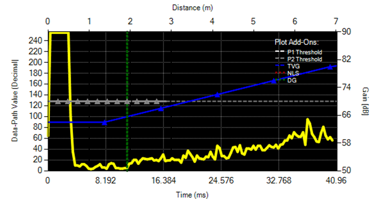
If the noise floor exceeds about 30% of the maximum value of 255 on the echo data dump, then too much gain is being applied. The TI factory gain ramps the TVG up to 90dB, which is not recommended for initial out-of-box evaluation; therefore, use the GUI defined Long or Short TVG presets, or shift the gain range to the next lower level. Try keeping the gain at a value to maintain a noise floor below a value of 80 out of 255 to enable the 3:1 SNR scaling and proper threshold mapping. The best SNR scaling profile is when the noise floor can be minimized to a value of 1 out of 255, while the echo peak return is nearly saturated at 254 out of 255.
|
Too much Time-Varying and/or Digital Gain nearly saturates the noise floor |
Ideal balance of Time-Varying and/or Digital Gain maintains the noise floor below a level of 80 (one third of the max level) |
Figure 23. Noise floor saturation
5.8. Can I copy my device settings from one PGA460 to another?
To save the PGA460 device settings, which includes the user EPPROM space and volatile threshold mappings, navigate to the GUI’s Memory Map page, and click the Save Grid icon. This will save the latest values of the PGA460’s memory to a text (.txt) file, which can be loaded onto other PGA460 devices when using the GUI. To ensure the latest device settings are pulled from the device, click the Read All icon before saving the grid.
To load the grid map text file to another device, click the Load Grid icon. If the Update Mode is set to Immediate, then the shadow registers will automatically be written to after being loaded from the text file. To burn the loaded EEPROM values, navigate to the Test Mode page, and click the Program EEPROM button.
5.9. I do not see any echo return peaks on my echo data dump.
If you do not see any echo returns, check the following:
- Is the record time length long enough to capture the distance equivalent to the target? If the object is at 5m, a minimum of 30ms record length is required. To determine the minimum record length required, use the Time-of-Flight converter on the GUI’s Utilities tab in the right panel.
Figure 24. Utilities tab Time-of-Flight Converter
- Is the PGA460 drive and receive frequency set to the same resonant frequency of the transducer? If the transducer is driven at a frequency outside of its resonant or center-frequency, then the transducer will not be generate any sound pressure level. Most transducers typically allow for +/-5kHz drive and receive drift before no measureable returns are detected and filtered out by the DSP’s band-pass filter.
- Are you supplying sufficient voltage to excite the transducer? Some transducers require at least half of the maximum driving voltage to transmit a measurable amount of sound pressure level. For example, a transducer rated for a maximum driving voltage of 120Vpp may require at least 60Vpp to capture short distance measurements. Driving the same transducer with 10Vpp will likely not produce any usable or detectable sound pressure level.
- Is the VPWR overvoltage protection disabling the driver block due to the overvoltage condition flagging high? If the voltage supplied at VPWR exceeds value set by the VPWR overvoltage protection setting, then the transmit block is disabled. To disable the VPWR overvoltage protection feature, maximize the VPWR_OV_TH bits to the equivalent of 28.3V. The VPWR pin should not be supplied more than 28V.
- Have you set a large enough pulse count to generate enough sound pressure level for detection? Sound pressure level ramps as the number of pulses increases. A single pulse will be difficult to detect, while a pulse count of 20 is close to the maximum number of pulses required to generate the peak-saturated amount of sound pressure level. In addition, and especially for closed-top transducers, the current limit cannot be too low. Otherwise, the equivalent peak-to-peak driver voltage may reduce below 50% of the maximum driving voltage the transducer is rated for. See the PGA460-Q1 Ultrasonic Module Hardware and Software Optimization application note for guidance on settings the pulse count and current limit, which both impact drive strength.
- Is your target large enough and/or reflective enough to return a sufficient amount of ultrasonic energy for the transducer to capture? See the PGA460-Q1 Ultrasonic Module Hardware and Software Optimization application note for important details on various target types.
- Have you applied a sufficient amount of gain? If your gain is too low, and the noise floor is at 0, then you can afford to apply more gain. Set your gain such that it minimizes the noise floor to a value between 4 and 10. Use the PGA460-Q1 Ultrasonic Module Hardware and Software Optimization application note for guidance on tuning the time varying gain and digital gain multipliers.
5.10.How do I successfully use a high-frequency transducer (180-480kHz) with the GUI?
To use a high-frequency transducer, follow these steps:
- On the General page in the Transmit block, check the Burst Frequency Range Shift box, select the high-frequency value of the transducer, and select the band-pass filter bandwidth for the DSP.
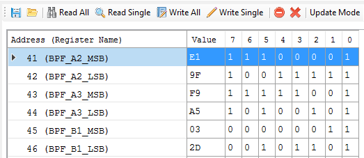
- On the Utilities tab of the right panel in the BPF Coefficient Calculator block, check the Shift Range, and select the same high frequency value of the transducer. The band-pass filter coefficient values A2, A3, and B1 will automatically update based on the transducer frequency and band-pass filter bandwidth.
- On the Memory Map page, copy the calculated coefficient values into the register addresses 0x41 to 0x46, and write these values to update the DSP.
The DSP is not automatically updated when the high-frequency mode is enabled, which is why the coefficient registers must be updated manually. After the coefficients are manually updated, any change to the frequency or band-pass filter bandwidth registers will overwrite the coefficients. Therefore, the coefficients must be rewritten any time a change is applied to these two registers. The coefficients are stored in volatile memory, thus the coefficients cannot be burned to the device, and must be written to at initialization, along with the threshold, and the final solution.
|
Step 1. Shift and set frequency and BPF-BW on General page |
|
Step 2. Shift and set frequency on BPF Coefficient Calculator |
|
Step 3. Write the coefficients from the calculator into the respective registers on the Memory Map page |
Figure 25. Steps to set and evaluate high-frequency transducers
5.11.How do I calculate the distance using the return data from the Ultrasonic Measurement Results command?
The PGA460 captures the interrupt time, and outputs the distance equivalent, width, and peak amplitude for up to eight returning echoes when the threshold is intersected. To solve for the time-of-flight, use velocity = distance / time. Since the speed of sound (velocity) is typically at a value of 343m/s at room temperature, and the PGA460 outputs the round-trip time at which the threshold is intersected in 1us resolution after bursting, the distance to the object is computed as the product of velocity and one-way time. The PGA460 specific equation to solve for distance in meters is as follows:
To account for the initial amount time spent bursting for a more accurate measurement:
Refer to the PGA460-Q1 Ultrasonic Module Hardware and Software Optimization application note for details on the how temperature changes the speed of sound, and how to how to fine-tune the velocity variable of the distance calculation. The on-board temperature sensor can be used to monitor the local ambient temperature at the device.
5.12.Is there any limitation in using One-Wire UART (OWU) mode on the GUI?
The GUI currently does not support evaluation of the One-Wire UART interface, though the hardware is in place to do so for future GUI updates. The GUI is able to set the PGA460 device into the One-Wire UART mode, but the GUI will only be able to transmit data. GUI is not able to process the return data once the OWU mode is set. An external micro controller must be used to both send and receive data. The PGA460 device cannot revert to standard UART once in the OWU mode. The EVM must be reset to use the GUI in UART mode again.
5.13.I am not able to detect an object using the Energia sketch, or the object distance is always the same.
The Energia sketch uses a fixed level threshold and a fixed level time varying gain. Try various combinations of setting the threshold and TVG to the different percent-from-maximum levels. The options include 25%, 50%, and 75% of the maximum. If no object is detected, increase the gain range or gain percentage. If the object distance is always the same, typically the same short distance value, increase the threshold or reduce the gain range or gain percentage. Fine-tuning of the hard-coded user EEPROM values may be required. The hard-coded values can be modified in the pga460_ussc.c library file.
6. Running the Hardware and Environmental Factors
6.1. There appears to be a continuous noise source present.
If you are using the listen-only command, and are recording a large noise floor on the echo data dump, an ultrasonic aggressor may be present in the immediate area. Common aggressors include ultrasonic based room occupancy sensors, AC power supplies for laptops or bench equipment, and harmonic noise from other user components on custom hardware (such as motor switching noise). Try isolating the transducer by shielding its field of view, running the EVM using only the laptop in USB-boost power mode (LP-USB populated on Alt Pwr Mode jumper block), and/or going to an electronically-quiet room or outdoors.
Figure 26. Murata MA40H1S-R noise floor saturated based on Listen-Only command in a room with 40kHz occupancy sensor
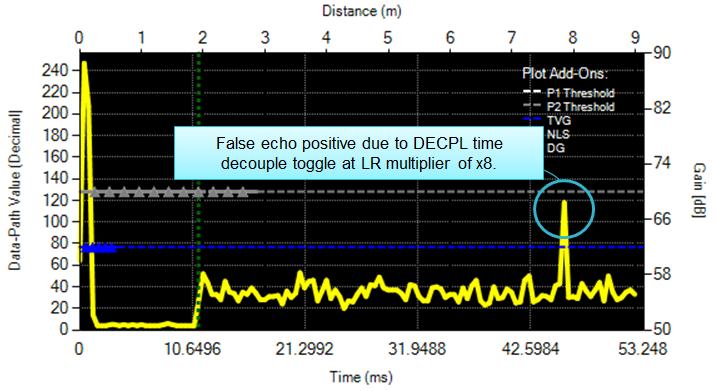
6.2. A false echo positive is always present at 7.7m, even when the transducer is disconnected. Why does the PGA460 detect this unreal artifact on the echo data dump?
If you are using the TI factory EEPROM settings, then the Time Decouple mode is enabled after 45.056ms from the time of bursting, or the distance equivalent of 7.7m. The toggling of the decoupling pin acts as an unintentional internal noise source, coupling onto the analog front end’s return path. As a result, this toggling depicts itself as a false echo positive. However, the decoupling feature can be useful if the transformer is continuously susceptible to noise from the environment, such as in industrial use-cases. If you do not intend on using the time decouple feature, maximize the enable time to 65.546ms. Otherwise, map the threshold around the decouple-produced peak, which will be fixed and repeatable. You may or may not be able to detect a real returning object at the same instance time decoupling is enabled, as this will depend on the returning echo’s strength.
Figure 27. Time decoupling toggle noise at 45.056ms
6.3. Motor switching noise appears to be coupling onto the ultrasonic return path, which increases the noise floor. How do I mitigate this noisy loading effect of the motors?
Running the motor without a propeller may actually result in worst case performance. A load (in this case, the propeller) is typically recommended to balance the driving torque of the DC motor with the magnetic field to induce a proper EMF. No load theoretically yields infinite speed, but realistically yields in unpredictable behavior. To mitigate noise form the motor switching, consider the following:
- External Filter with RINP
- Optimize the RINP resistor in series to the CINP capacitor. The value of this resistor may be between 100Ω to 3kΩ. The addition of a series resistance improves noise rejection and filtering at the return path’s input to the PGA460’s AFE without impeding peak return performance. This additional resistance will also improve Bulk Current Injection (BCI) robustness.
- Pulse Count
- For the long distance measurements, increase the pulse count to the maximum allowable value to generate peak returns and width. 20 pulses is a typical maximum for peak sound pressure level, or allowable pulse count for closed-top transducers. To further increase the width of the echo return, maximize the pulse count to the PGA460 maximum supported count of 31 pulses for appropriately rated transducers.
- Transducer Driving Voltage
- Maximize the driving voltage of the transducer to generate peak sound pressure level.
- Tuning Transducer Frequency
- Fine-tune the transducer’s frequency to maximize the sound pressure level emitted. See the PGA460-Q1 Ultrasonic Module Hardware and Software Optimization application note to view an example of how much of an impact frequency can have on peak performance.
- Four Layer Board Option
- Additional grounding layers will help with noise rejection on the board level.
- Motor Switching Frequency
- Because the most influential factor is the motor switching frequency, increasing the motor frequency to be at least 8 kHz beyond the nominal center frequency of the transducer will prevent the PGA460 noise floor from saturating. If the switching frequency is greater than the resonant frequency, there is no likelihood that harmonics will interfere with the transducer’s performance.
- Conductive Shielding
- Use conductive shielding to ground and surround the ultrasonic enclosure such that the noise is absorbed by the shielding, rather than coupling onto the ultrasonic module’s board, cables, transformer, or transducer.
- Alternative Transducer
- Use a transducer outside the range of motor switching or motor switching harmonics.
6.4. In transformer driven mode, the secondary voltage appears as a distorted sinusoidal waveform. How do I clean-up my driver signal exciting the transducer?
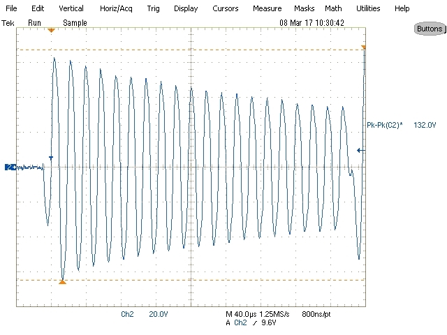
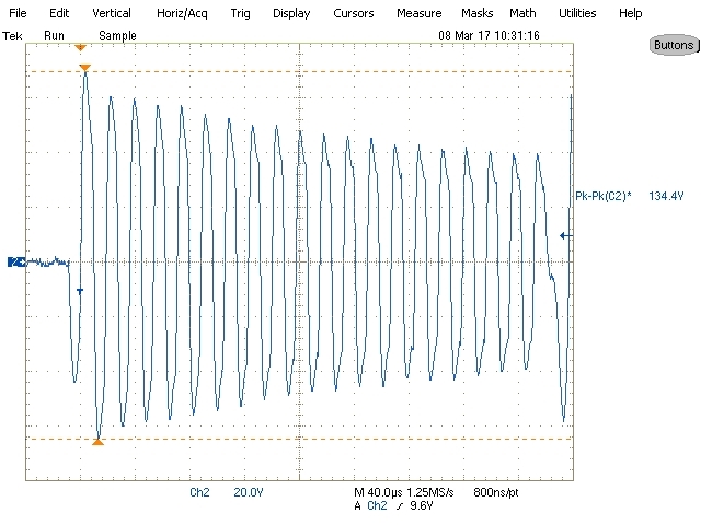
The most influential variables responsible for forming the sinusoidal driver at the transducer are the external tuning capacitor and damping resistor values. See the PGA460-Q1 Ultrasonic Module Hardware and Software Optimization application report for details on selecting these values. The current limit can also impact driver cleanliness. If the transformer is saturated through the primary windings, then distortion will be present at the peaks of the waveform. Reduce the current limit until the peak is no longer distorted, but still maximized in peak-to-peak amplitude. Though a clean driver is ideal, more sound pressure level is still be generated from a larger peak-to-peak distorted sinusoidal waveform. Ensure the current limit is enabled in transformer driven mode.
Figure 28. Transducer Driver Waveform Smoothness
6.5. I can hear an audible clicking sound from the ultrasonic sensor. Is this normal?
An audible clicking noise may be heard when driving the transducer, especially in the transformer driven mode. This typically indicates that the sensor is being driven at the maximum supported power, but can also indicate that the sensor is being overdriven. As long as the current limit is applied, the transformer saturation current is not exceeded, the transducer driving voltage specification is not exceeded, and the pulse count is limited, there is no reason to be concerned. The noise is mainly an artifact of the excitation mechanics of the transducer.
6.6. How can I determine the characteristics of my transducer if no datasheet is provided, or I do not have an impedance gain-phase analyzer?
The transducer’s frequency diagnostic feature enables the PGA460 to measure the resonant frequency of the transducer during post-burst decay. This can be used to find or optimize the PGA460 driving frequency to match the resonant frequency of the transducer to produce the maximum amount of sound pressure level for long range applications. Sweep the frequency diagnostic’s window length and start time parameters to collect an averaged representation of the transducer’s resonance. Properly settings these parameters also allow for any drive-to-release detuning to subside, which is typically observed immediately after releasing the driver. See the PGA460-Q1 Ultrasonic Module Hardware and Software Optimization for details on how much of an impact the PGA460 set frequency has on the returning echo’s peak amplitude.
6.7. Does the USB-Boost circuit limit my sensor’s overall driver strength?
The input to the USB boost circuit is current limited so that the under voltage condition at VPWR is not flagged high after a maximum current (500mA) limited burst-and-listen command. As a result of this limiting precaution, the driver strength starts to saturate at approximately 350mA when powering the BOOSTXL-PGA460 from the USB boost circuit. If the transducer requires more than 350mA to generate the maximum amount of sound pressure level, then an external supply should be used to power the BOOSTXL-PGA460 instead. The USB boost circuit is ideal for initial mid-range evaluation and demonstration purposes, but should not be used as the power source to optimize and calibrate the end system, unless the end system uses the same or similar boost circuit.
|
300mA current limit |
500mA current limit |
Figure 29. Driver strength saturation of USB boost circuit
6.8. When should I use the Disable Current Limit feature?
Disabling the current limit is only recommended for direct driven mode or high-frequency (180 to 480 kHz) transducer evaluation. Do not disable the current limit for transformer driven mode, because the PGA460’s internal nMOS FETS are only rated for 500mA. Transformers typically paired with the PGA460 are able to generate 2A of sink current without a limit.
7. Best Practices
7.1. The laptop’s AC power supply raises the noise floor.
When using the USB boost circuit to power the PGA460-Q1 EVM, the laptop’s AC power adapter may raise the PGA460’s noise floor. This ultimately depends on how stable the AC power adapter is. To prevent the AC power adapter from possibly influencing the noise floor, isolate and power the laptop from battery only.
7.2. When in doubt, restart the GUI and hardware.
If the EVM hardware is disconnected or unpowered while the GUI is open, or the GUI starts to respond abnormally, TI recommends to fully restart the GUI to ensure the PGA460 device settings are updated and reference the most recent values.
7.3. Use the small form factor reference design as your system’s solution.
Due to the large size of the EVM, mounting the EVM to a real system for test purposes can be a challenge. To better represent the small size of an ultrasonic module, TI offers the PGA460-Q1 Small Form Factor (PGA460Q1SFF) module variant reference design for system integration and testing.


