This thread has been locked.

If you have a related question, please click the "Ask a related question" button in the top right corner. The newly created question will be automatically linked to this question.

TDC7200: TDC7200

Part Number: TDC7200

Dear all,

I am try to test how to measurement timing by tdc7200.

1. I am using default seting.

2. I using 1 GPIO from MCU to generate START signal to Pin 3, and delay around 10ms and generate STOP signal to Pin 4.

I hope that Interrupt signal at Pin 8 must go low but it do not. And I see that, I only go low when I read/write data of tdc7200 via SPI

Any idea how to test it? 

p/s I am using 13Mhz at pin 5 and read/write data at register is correct now.

Thanks and regards

  • Hello,

    To start measuring, you must set the START_MEAS bit in the CONFIG1 register. This will output a signal on the TRIGGER pin that can be sent to your MCU to begin your start and stop pulses.

    Also, keep in mind that the max measurement period is only 5ms for a 13Mhz clock.

    Regards,
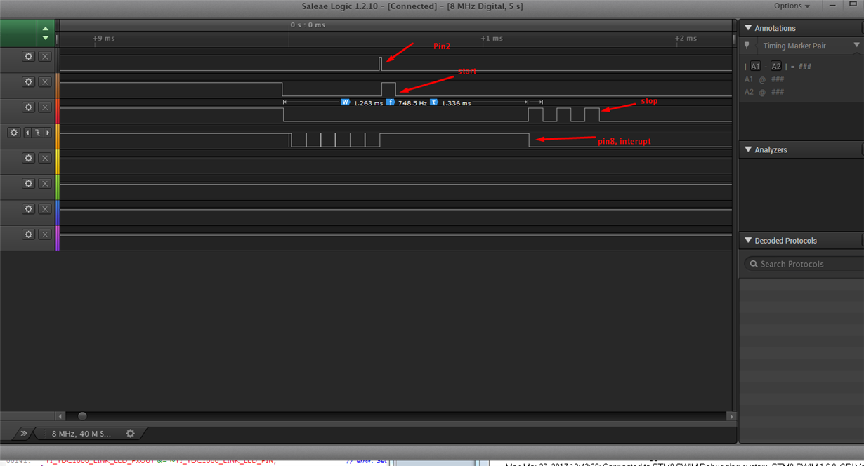
  • Here is my result:

    Pin 2 is TRIGG OUT, it high after I set START_MEAS bit for CONFIG1 = 0x03 (mode 2)

    after that I set start signal at Pin 3, wait around 0.7ms and generate stop signal at pin 4.

    I see that pin 8 is low after stop signal to high. But I read result at register TIMER 1 0x10 alway is 0.

    Do you think the signal is good now?