This thread has been locked.

If you have a related question, please click the "Ask a related question" button in the top right corner. The newly created question will be automatically linked to this question.

AFE5818: AFE5818 SPI functionality

Part Number: AFE5818

Hi,

We have a PCB with two AFE5818, both have the same electrical schematic configuration and share the same power supplies.

One of them is not responding to our SPI communication.

- All SPI signals are the same on both AFE’s

- I/O’s are configured correctly

- power supply ripple on all rails is <20mV

- No power drop was detected on all rails after configuration and Power Down pin release.

- Clock seems to behave the same on both AFE’s

- We tried connecting all AFE2 to AFE1 signals  (except for their SDO)

- AFE1 SDO on power-up measure approx. 0.3v while the BAD AFE2 SDO is 1.8v


Attached plot screen shot and layout & schematics.
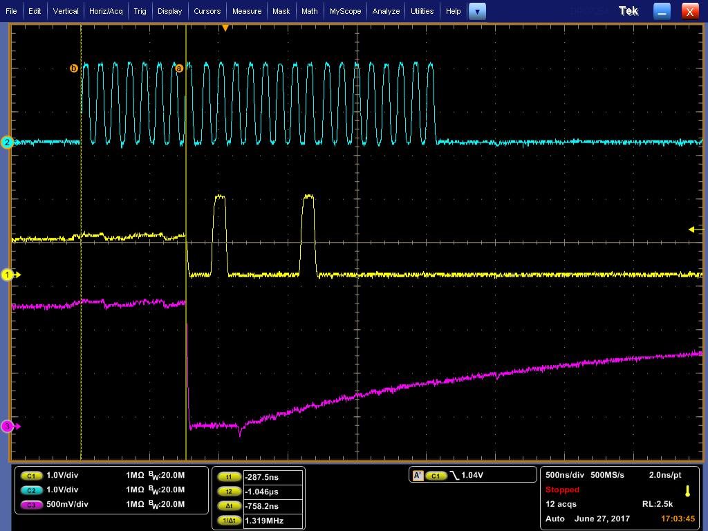
I would appreciate your help with this issue, or even a hint on what could make the 2nd AFE act the way it does (drops as the 1st is doing, and  immediately release the line)


Best Regards,


Rotem


Edit: Design files removed as per customer request.

  • Hi Rotem,

    Are you sure it is okay to share your design files in an open/public forum where anybody can access it?
    Your schematics show the same nets for both AFE5818's SPI pins (even SEN). Please make sure they are not shorted internally on the board.

    You also did not show the SEN signal and the 2nd AFE5818's SPI signals in your oscilloscope capture--please add that and also label the scope channels.
    If you are still having problems after verifying that the SEN pins are separate for each AFE5818, try testing SPI on each AFE5818 separately then we'll go from there.

    Sincerely,
    Olu

  • Hi Olu,

    I wasn't aware it will be viewable to all...can you please remove it?
    I'll check your feedback and advise.

    BR,

    Rotem
  • Hi Rotem,

    I removed the design files as you requested. Regarding SPI on the AFE5818, when there are multiple AFE5818 slaves connected to the same master SPI device, we generally have the slaves share all SPI lines except SEN.
    That way, the slaves can share the same SPI bus since only one slave can communicate to the master at a time (when its own separate SEN line is active).

    Sincerely,
    Olu

  • Hi Olu,

    Customer followed all you hints and advise with no change in results...

    Can we arrange a conference call?

    Feel free to contact me directly - rotem.sasporta@ebv.com

    BR,

    Rotem

  • Hi Rotem,

    That is not likely to happen anytime soon with my current schedule. Do you have the scope shots of the SEN signals (with both signals not active at the same time) and the rest of the SPI lines?

    Sincerely,

    Olu

  • *****6th of July update****

    Hi Olu, 

    Please see below update:

    As we continue investigating,

    Using the following sequence both AFE’s are responding:


    -        Power up – Both AFE’s at full PWD    (PWD_GBL = PWD_FAST = ‘1’)

    -        Init Clock distributer

    -        Both AFE’s PWD_GBL = 0

    -        Reset both AFE’s

    -        Init Both AFE’s

    -        Reading from both AFE’s = Success

    -        Release AFE1 or AFE2 PWD_FAST = ‘0’

    -        Reading AFE1 = Success, AFE2 = FAIL


    In order to get AFE2 responding again (Without a new power up):

    -        AFE2 PWD_FAST = ‘1’

    -        AFE2 Reset

    -        AFE2 Init

    -        Reading from both AFE’s = Success


    I’m beginning to think it is in the AFE Initialization 

    your thoughts?

    BR,

    Rotem

    -----------------------------------------------------------------------------------------------------------------------------------------------------------------------------------------------------------------------------------------------------

    Hi Olu,

    I need to send you some more info, can we move to emails?

    Please see below update:

      1. We’ve removed the 1st AFE, and the second is always responding.


      1. We’ve also done the following sequence and both AFE’s are communicating (each has its own separate SEN).


    • Power-UP

    All FPGA SPI signals are at Input

    Both AFE’s PWD_GBL and PWD_FAST are at ‘1’

    • Both GBL_PWD = ‘0’

    • Reset both AFE’s

    • Initialize both AFE’s via SPI

    • Reading from AFE’s sequentially = Success


    • NOW, when lowering one of the PWD_FAST = ‘0’, the 2nd AFE stops communicating but the 1st continue responding (even after lowering its PWD_FAST)


      1. We’ve looked for voltage dropping on 1V8, and 1V2 rails vs. pulling PWD_FAST low, but didn’t find it. 1V2 ripple is increasing to <40mV (which is expected from a dcdc).


      1. I don’t know if the following is related, but I’ve changed all 10nF at the input to 0.1uF (as the datasheet ‘Pin Functions’ section suggest) and AFE2 3v3_A is now shorting


    Do you now have a clue on what could be happening?


    And now with some pictures


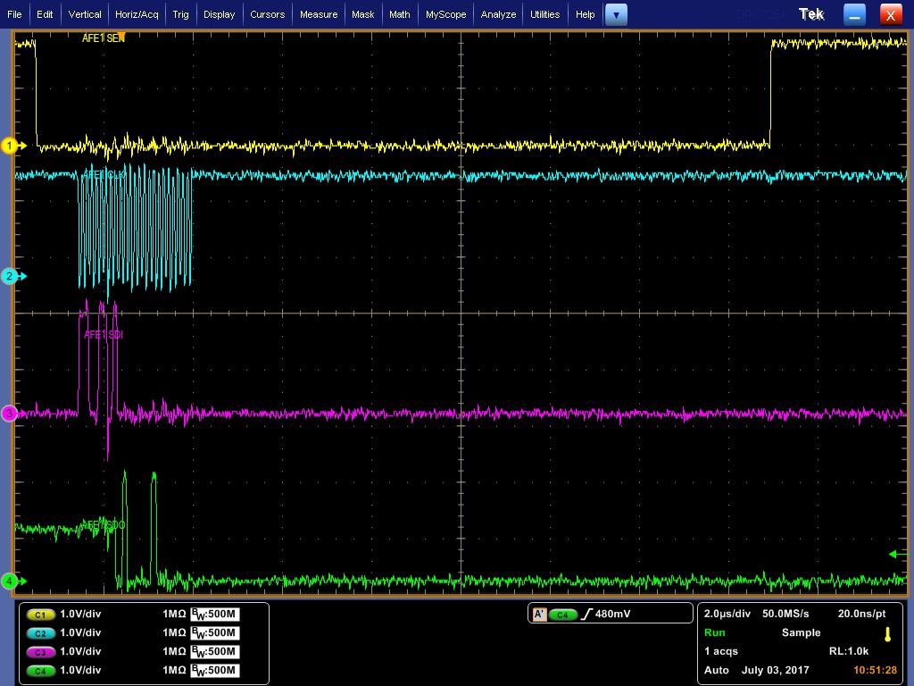
    AFE1 SPI read:

    Preforming a read on AFE1 and its acknowledge.


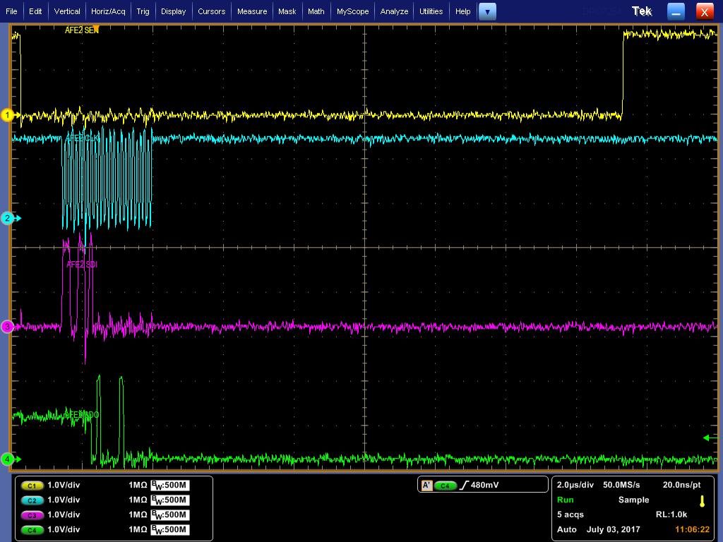
    AFE2 SPI read:

    Preforming a read on AFE1 and its acknowledge

    AFE2 only acknowledge when both PWD_FAST = ‘1’, and only if not releasing one of the PWD_FAST to ‘0’


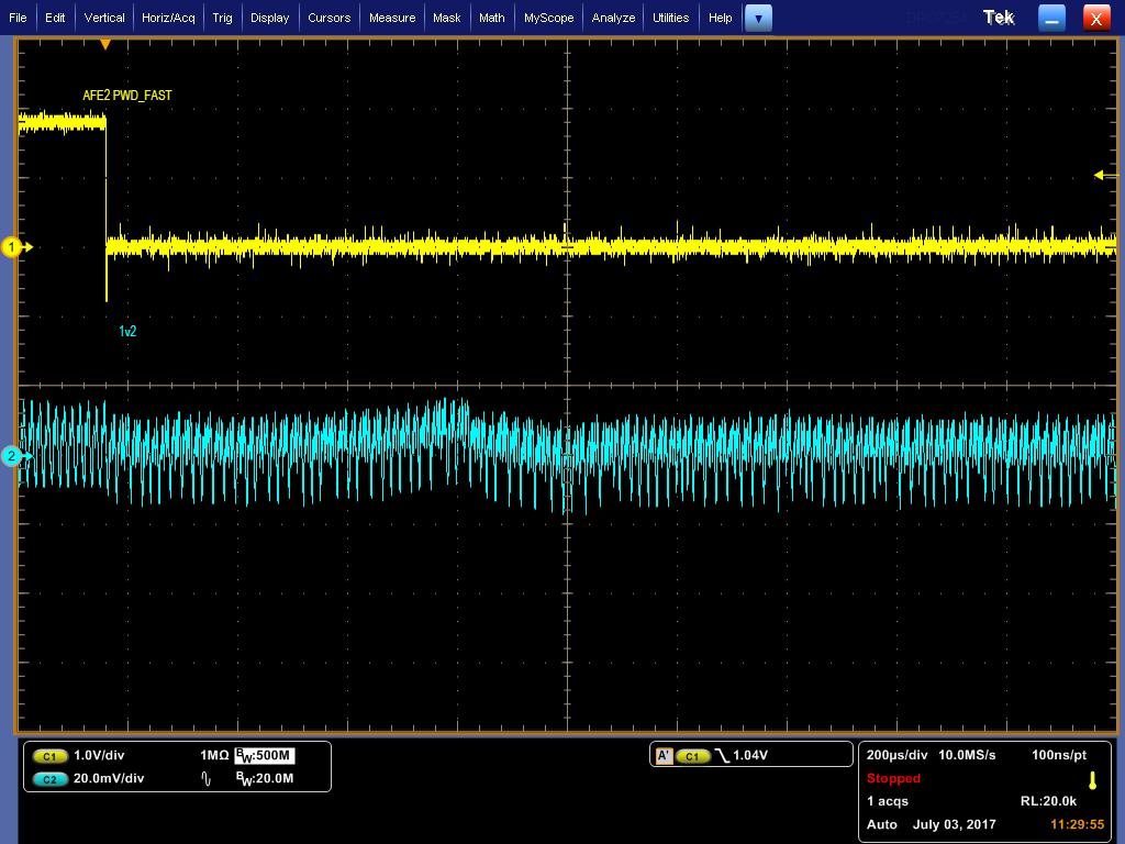
    AFE2 PWD_FAST vs 1v2:

    PWD_FAST going low and what happens on 1v2 rail.


    AFE2 PWD_FAST vs 1v8:

    PWD_FAST going low and what happens on 1v8 rail.


    AFE2 PWD_FAST vs 1v8_A:

    PWD_FAST going low and what happens on 1v8_A rail.


    AFE2 PWD_FAST vs 1v8 5msecTB:

    PWD_FAST going low and what happens on 1v8_A rail. Time base shows 5msec.


    AFE2 PWD_FAST vs 3v3_A 500MHz BW:

    PWD_FAST going low and what happens on 3v3_A rail.


    AFE2 PWD_FAST vs 3v3_A 5msecTB:

    PWD_FAST going low and what happens on 3v3_A rail. Time base shows 5msec.


    AFE2 PWD_FAST vs 5v_A:

    PWD_FAST going low and what happens on 5v_A rail.


    AFE2 PWD_FAST vs 5v_A 5msecTB:

    PWD_FAST going low and what happens on 5v_A rail. Time base shows 5msec.


    BR,


    Rotem

  • Hi Rotem,

    Your AFE2_3.3V should not be shorting because you changed input capacitors. Please make sure there is no errant solder on the board causing a short somewhere.

    Are you saying that your AFEs can communicate fine via SPI when PDN_GBL is asserted but stop communicating once it is deasserted? That is very peculiar behavior.

    If you have an unexpected short on the AFE2 side of your board, it is possible that when PDN_GBL is asserted, the circuit using the shorted supply is also powered down leading to no issues but once that circuit is active, it causes problems with AFE2.

    And I think plots showing what happens to AFE2's supplies when PDN_GBL is deasserted would provide better information.

    Tables 7 and 8 in the datasheet go over some of the circuitry controlled by the PDN_GBL and PDN_FAST pins.  

    Sincerely,

    Olu