This thread has been locked.

If you have a related question, please click the "Ask a related question" button in the top right corner. The newly created question will be automatically linked to this question.

TDC1000-GASEVM: Incorrect TOF measurement with 175KHz air transducers

Part Number: TDC1000-GASEVM

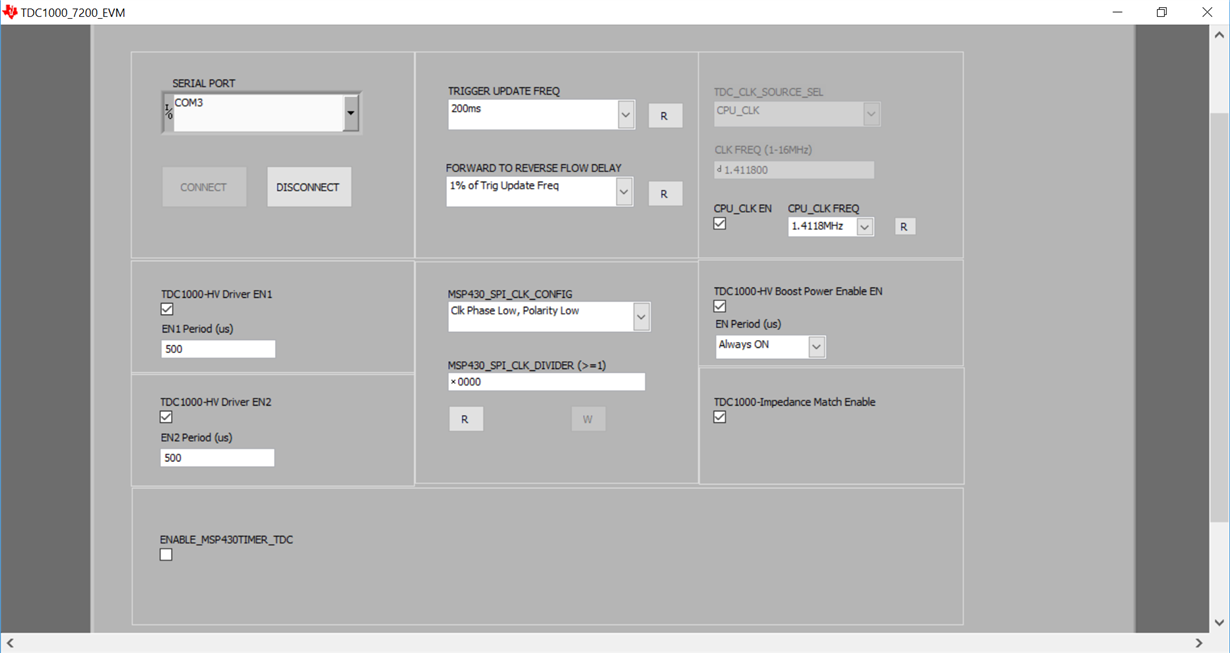
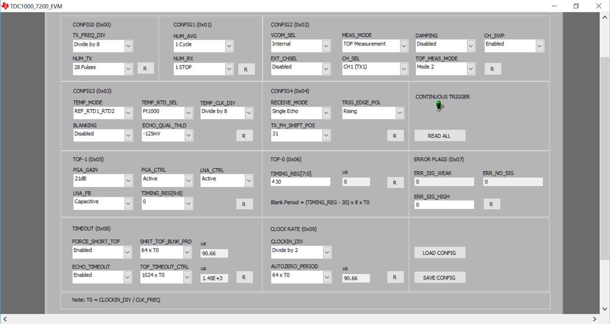
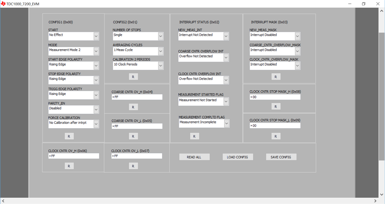
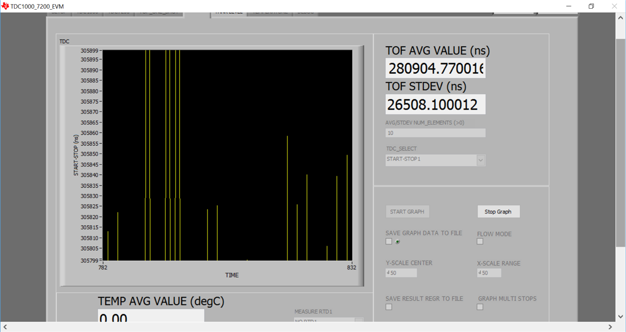
I am using a 175 KHz transducer in an anemometer project and having issues with the TOF measurement with my setup.   With the attached configuration, the TOF measurement and std don't appear correct for sea level, 20C at a distance of 7.62cm between transducers.   I've mounted the transducers so the LOS between the two are clear of obstructions.   Can you please advise?

http://www.newark.com/multicomp/mcusd19a175b11-5rs/transceiver-175khz-19mm-metal/dp/17X2016

  • Hi Anthony,

    First I would uncheck the TDC1000 Impedance Match enable on the setup tab. Also, try decreasing the HV driver EN period. With 28 pulses at 175khz, your excitation period is only about 160us. You could set it to 200us to add a bit of buffer. Start there, and monitor your START, STOP, and COMPIN signals with an oscilloscope. This will give you a better idea of whether your STOPs are triggering properly.

    Regards,

  • Hi Scott,

    I unchecked the Imp Match box and decreased the EN period to 200 us. I'm still having the same issue. When I do get things configured to a point where I can get a stop signal and TOF, I think its actually induced by noise triggering the stop because when I move the change the transducer distance, the COMP signal doesn't shift and TOF remains the same. Any other guidance?

    I tried the same with 40 KHz transducers, adjusting times to what I saw fit and I am having a similar problem. Can you propose a setup/config for me to try to get this working (config file, transducer distance, etc)?

    Thanks,
    Anthony
  • Some additional findings. I simplified my setup to make sure it wasn't an issue on the transducer end. I used 40Khz transducers, in mode 2, varying pulse number (5-30), varying distance (6cm->20cm) and monitoring TX pulses and the RX transducer echo unconnected to the board. I am able to see the response echo just fine and it appears to have the correct delay for each of the distances. Echo pk-to-pk seems to be in the 60-100mv range which I suspect is normal for waterproof, sealed transducers without any amplification.

    At this point, I've modified settings and time durations on the eval board to many configurations but still can't make sense of the Comp signal and TOF returned. Can you please provide a configuration to get this working (config file, transducer distance, 40 Khz, etc)?
  • Does anyone have any guidance?   Just a general config for two 40Khz transducers mounted straight across from each others a specified distance in the air would get me on the right track.   I can't seem to get a reliable comp in signal.

  • Hi Anthony,

    To start with, you will need to modify the bandpass filter on the receive path between the PGA output and COMPIN. The GASEVM bandpass filter is set for 58khz-300khz. You may still see some signal, but it will be very difficult to get a good SNR outside of the passband of the filter.

    I've attached a setup file to try. You will likely need to play with the blanking settings, but this will give you a start.

    TDC1000GAS_Setup.txt
    TDC1000_Config0                         9C
    TDC1000_Config1                         00
    TDC1000_Config2                         02
    TDC1000_Config3                         00
    TDC1000_Config4                         00
    TDC1000_TOF-1                           60
    TDC1000_TOF-0                           1E
    TDC1000_Error_Flags                     00
    TDC1000_Timeout                         1B
    TDC1000_Clock_Rate                      00
    TDC1000_Conts_Trigger                   00
    TDC7200_Config1                         00
    TDC7200_Config2                         00
    TDC7200_Interrupt_Status                00
    TDC7200_Interrupt_Mask                  00
    TDC7200_Coarse_Cntr_Ov_H                FF
    TDC7200_Coarse_Cntr_Ov_L                FF
    TDC7200_Clock_Cntr_Ov_H                 FF
    TDC7200_Clock_Cntr_Ov_L                 FF
    TDC7200_Clock_Cntr_Stop_Mask_H          00
    TDC7200_Clock_Cntr_Stop_Mask_L          00
    TRIGGER_UPDATE_FREQ                     0001
    TDC_AVG/STDEV_NUM_ELEMS                 000A
    SAVE_GRAPH_DATA_TO_FILE                 00
    FLOW_MODE_SELECT                        00
    Y-SCALE_CENTER                          0032
    X-SCALE_RANGE                           0032
    MEASURE_RTD1                            00
    SAVE_RESULT_REGR_TO_FILE                00
    GRAPH_MULTI_STOPS                       00
    TDC_SELECT                              00
    TEMP_RTD_SELECT                         00
    TEMP_RTD_MODE                           01
    TEMP_AVG/STDEV_NUM_ELEMS                000A
    SAVE_TEMP_DATA                          00
    GRAPH_YMAX_DATA                         00000000004C4B40
    GRAPH_YMIN_DATA                         0000000000030D40
    TDC1000-HV_DRV_EN1                      01
    TDC1000-HV_DRV_EN2                      01
    HV_DRV_EN1_Period                       02BC
    HV_DRV_EN2_Period                       02BC
    ENABLE_POWER_CYCLE                      00
    CLK_FREQ_(1-16MHz)                      1.263200
    CLK_SOURCE_SEL                          03
    CPU_CLK_FREQ                            05
    CPU_CLK_EN                              01
    TDC1000-HV_BST_PWR_EN                   01
    HV_BST_PWR_EN_Period                    0000
    FWD2REV_FLOW_DELAY                      0000
    TDC1000-IMPE_MATCH_EN                   00
    ENABLE_UART_STREAM                      00
    ENABLE_MSP430TIMER_TDC                  00

  • Hi Anthony,

    Were you able to get this working?

    Regards,