This thread has been locked.

If you have a related question, please click the "Ask a related question" button in the top right corner. The newly created question will be automatically linked to this question.

PGA460-Q1: PGA460-Q1

Part Number: PGA460-Q1

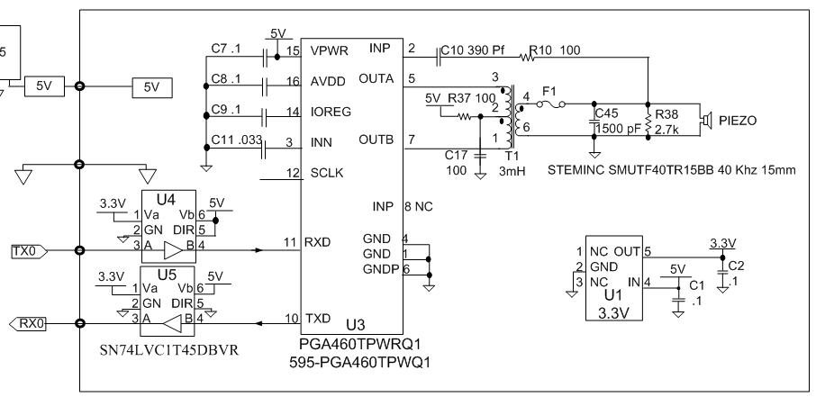
We use this circuit and have a Very difficult time communicating with different chips.  It seems that the 9600 baud timing must be exact or it will not communicate.  Sometimes it works perfectly.  Some PGA work in this circuit and some do not.  RX data can be seen on the scope but there is no TX data.

=Do you see anything wrong with this circuit?
=Does the 9600 baud need to be precision?  We have never had problems with other devices and the data shows up on monitors.
=Is 5V the ideal power to use on pin 15 and 5V for RX, TX (we have tried up to 5.5V and no improvement)?
=There is no activity on the OUTA and OUTB when we are able to send BURST/LISTEN.  Is something missing from the circuit?

Thanks, Peter

  • Hi Peter,
    Assuming your master controller (TX0 and RX0) is operating at 3.3V logic levels, you do not need the SN74 device. The PGA460-Q1 by default operates in a 3.3V logic level mode on TXD and RXD when the TEST pin is floating or pulled-down to GND. Your schematic shows TEST (pin 8, incorrectly labeled as a redundant INP on your schematic) as floating. Therefore, the 5V logic level is not necessary, and may be the root problem of your baud rate issue. Try removing and bypassing the SN74 to determine if this eliminates the baud rate sensitivity.

    Here is the datasheet description on how to use the test pin to set the logic level reference:
    The digital voltage-level selection performed by the TEST pin is executed at device power up. On power-up, the
    device checks the level of the TEST pin. If the level is low, the digital output pins operate at 3.3 V. If the TEST
    pin is tied high (3.3 V or 5 V are both considered high state), the digital output pins operate at a 5 V. This
    condition is latched in the PGA460-Q1 device so that the test mux can further use the TEST pin as previously
    described. If the application requires that a 5-V digital output is used and a test mux output must be extracted
    from the PGA460-Q1 device, then a weak pullup resistor on the TEST pin can be connected as shown in
    Figure 40.
  • Still no luck.

    We have tried removing the SN74 drivers and exactly copied the voltages on the TI PGA demo board.
    Command below is 55 c9 1c 1a which is read frequency.

    We can communicate with this same chip using toggle switches from the TI Dev software and it works perfectly.
    We can download all and send Listen commands and read responses when tied into the TI dev board using toggle switch.
    PGA will not respond when the toggle switch is going to our MSP based device.
    PGA will respond when toggled to the TI Dev board dev board does something slightly different.

    Does IO have to be hi or low on power up to enable RX TX?  We have left it open and tied it hi.
    We have tried 3.3V and 5V logic on the Test pin.
    We grounded SCLK thinking it was noise.
    Is there anything that can cause it to ignore RX TX such as a configuration register or wake?
    What other than baud rate can cause it to ignore the RX TX ?

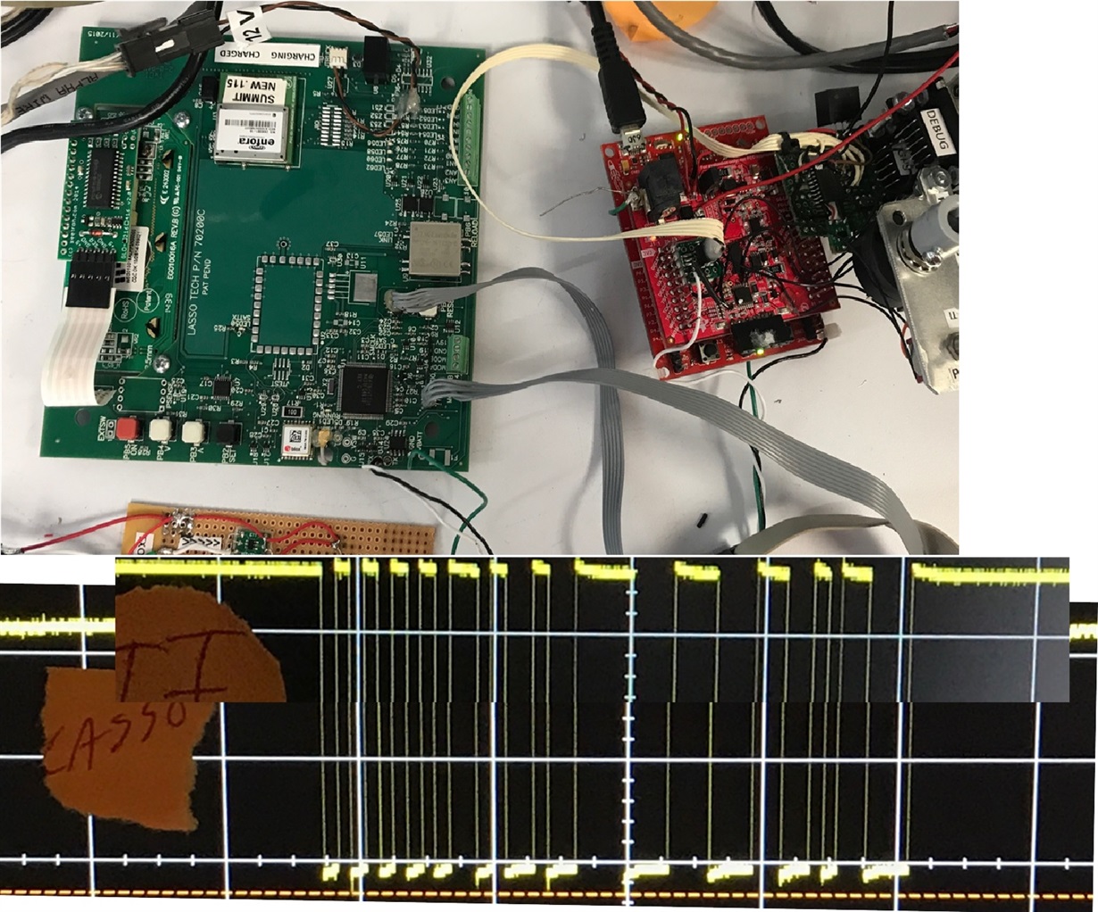
    Below are traces from the TI Dev board and our MSP based Lasso device generating 55 c9 1c 1a.  Timing seems to be the same.
    We rarely get this stumped.  Thanks for all of your help.

  • We found the problem with communication.  We needed to add a slight delay between RX characters.  It was on the edge so that is probably why it worked on some chips and not others.  Thanks, Peter

  • Hi Peter,
    I'm glad you able to resolve your communication issue. How much of a delay was necessary between RX characters? Are you saying that you are having to violate the standard UART format?

    To answer some of your earlier questions:

    Does IO have to be hi or low on power up to enable RX TX? We have left it open and tied it hi.
    [AW]: No, IO can remain floating if not used.

    We have tried 3.3V and 5V logic on the Test pin.
    We grounded SCLK thinking it was noise.
    [AW]: Yes, pulling SCLK to ground via a 10kOhm resistor is recommended if the synchronous mode is not used.

    Is there anything that can cause it to ignore RX TX such as a configuration register or wake? What other than baud rate can cause it to ignore the RX TX ?
    [AW]: The only issue in software is typically related to stop bits, UART_ADDR, or checksum, but you had already confirmed these to be correct.

    If another user encounters this issue, I'll have another check for them to perform. Thanks for the update!
  • Akeem,  We had to add about half of a stop bit.  It took a long time to find and 30 seconds to fix even thought the timing looked perfect.  

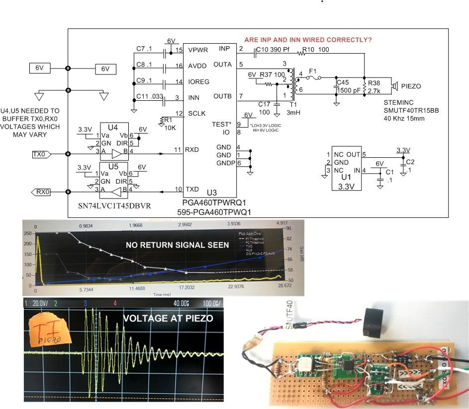
    The last struggle is: We have a rough breadboard before we make the final pre-production board to make sure it roughly works.  The TI Dev software and our MSP430 cannot detect the returned signal.  Is the Return INP and INN schematic correct below?  Thanks, Peter

  • We replaced the PGA after INP was shorted and are able to read the distance using the TI Dev system when we toggle switch the RX TX to the laptop so the prototype board above works and INP is not a problem.

    Bad news is that we Again cannot communicate using RX and TX using our MSP430, just as in the past after we installed the new PGA. In hindsight, this is the 3rd new PGA that suddenly works for no good reason. Once it works, it works every time unless replaced.
    Delay between characters was not a fix but it suddenly worked when we added the delay. Somewhere, it "enables" the RX and TX but I don't know how. We are sending 55 c9 1c 1a to read frequency but no response. We can toggle switch to the TI Dev software and it immediately communicates no problem. Very odd.

    Device Address, EPROM enable, Wiring....?? (it is very cool when it does work) Thanks