This thread has been locked.

If you have a related question, please click the "Ask a related question" button in the top right corner. The newly created question will be automatically linked to this question.

WEBENCH® Tools/TDC1000-GASEVM: Problem with tdc1000-7200-evm software

Part Number: TDC1000-GASEVM

Tool/software: WEBENCH® Design Tools

In the beginning I am sorry for my bad english.

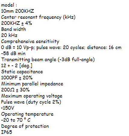
‎I have a tdc1000-gasevm board and sensors with the following features:

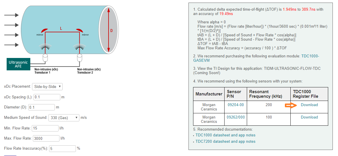
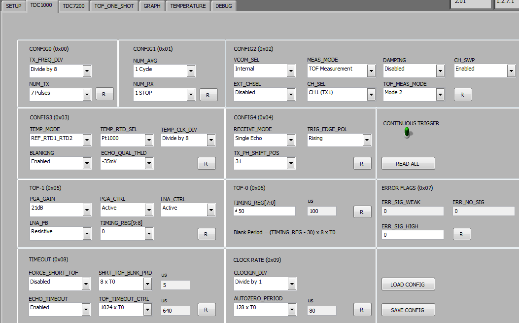
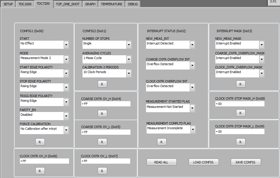
I want to make a gas flow meter.I uploaded the file generated by the webench designer in the tdc1000-7200 software. In the picture below, you can see my settings:

The tdc1000-7200 software seems to require 49 parameters, but the number of parameters within the generated file is 46.
I realized that these parameters are TDC1000-HV_BST_PWR_EN ,HV_BST_PWR_EN_Period ,FWD2REV_FLOW_DELAY
I entered these parameters manually:

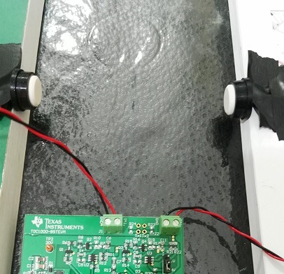
I placed the sensors at a distance of 10cm:

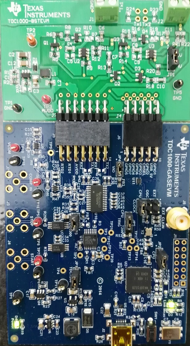
I put jumpers in the following way:

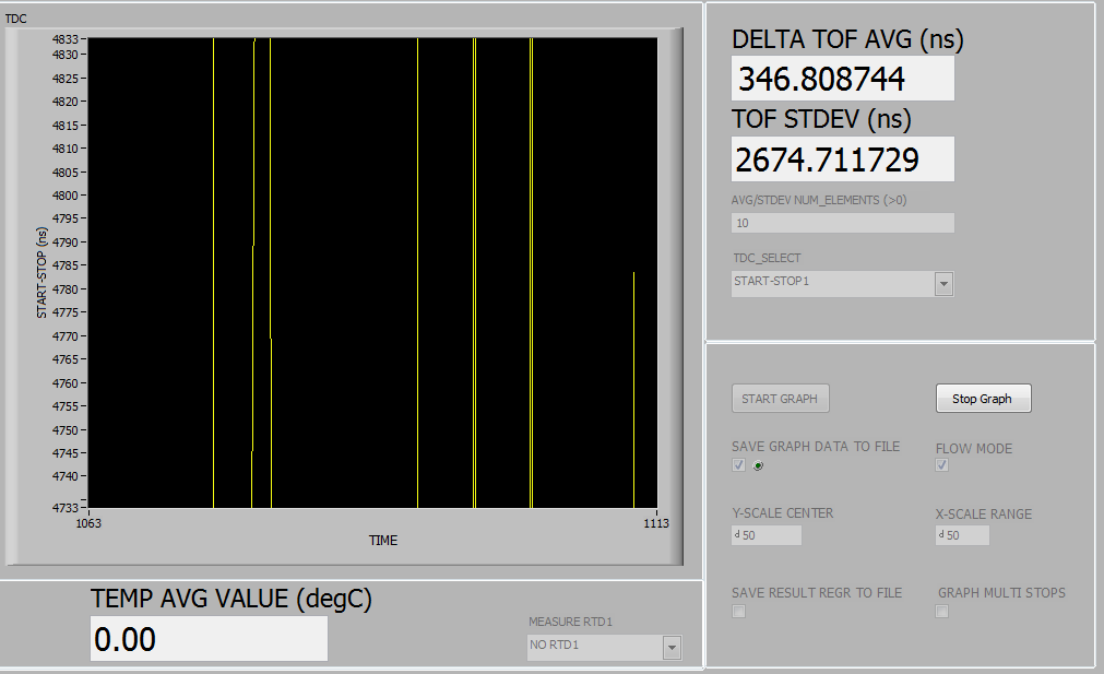
In the csv file, the numbers for the start_to_stop1 column have been severe changes (no flow exists)

Results based on start to stop1.xlsx

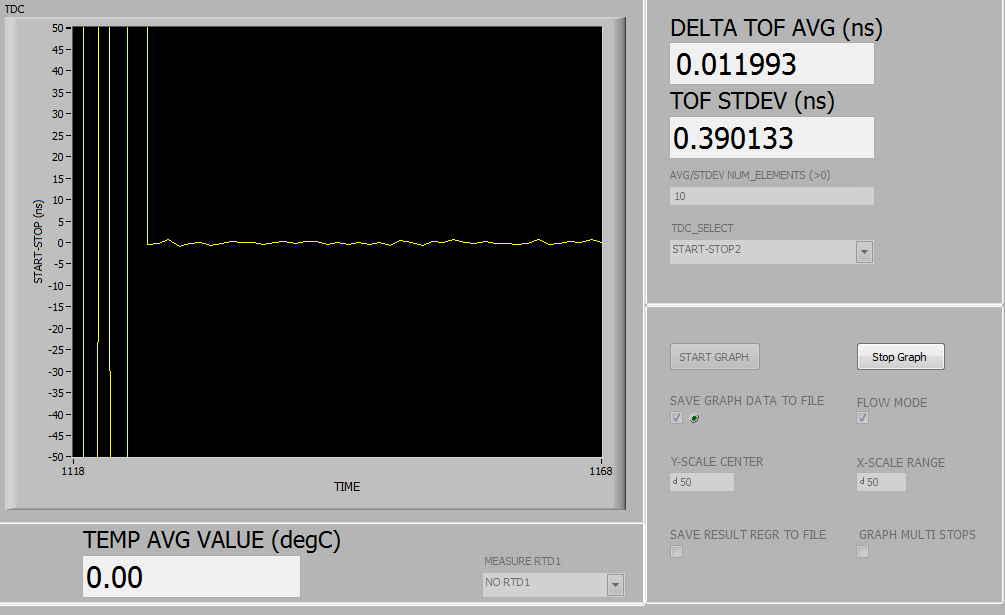
So I chose start_to_stop2 in the tdc_select. The chart is as follows. But when I was flowing through the sensors with a hair dryer, there was no change in the chart

Results based on start to stop2.xlsx

RegisterFiles-TDC1000_RegFile_GasFlow_200kHz_MorganCeramics_20141218 (File generated by webench designer).txt
TDC1000_Config0                         47
TDC1000_Config1                         41
TDC1000_Config2                         12
TDC1000_Config3                         08
TDC1000_Config4                         1F
TDC1000_TOF-1                           E4
TDC1000_TOF-0                           32
TDC1000_Error_Flags                     00
TDC1000_Timeout                         03
TDC1000_Clock_Rate                      01
TDC1000_Conts_Trigger                   01
TDC7200_Config1                         02
TDC7200_Config2                         40
TDC7200_Interrupt_Status                07
TDC7200_Interrupt_Mask                  07
TDC7200_Coarse_Cntr_Ov_H                FF
TDC7200_Coarse_Cntr_Ov_L                FF
TDC7200_Clock_Cntr_Ov_H                 FF
TDC7200_Clock_Cntr_Ov_L                 FF
TDC7200_Clock_Cntr_Stop_Mask_H          00
TDC7200_Clock_Cntr_Stop_Mask_L          00
TRIGGER_UPDATE_FREQ                     0001
TDC_AVG/STDEV_NUM_ELEMS                 000A
SAVE_GRAPH_DATA_TO_FILE                 00
FLOW_MODE_SELECT                        00
Y-SCALE_CENTER                          0032
X-SCALE_RANGE                           0032
MEASURE_RTD1                            00
SAVE_RESULT_REGR_TO_FILE                00
GRAPH_MULTI_STOPS                       00
TDC_SELECT                              00
TEMP_RTD_SELECT                         00
TEMP_RTD_MODE                           01
TEMP_AVG/STDEV_NUM_ELEMS                000A
SAVE_TEMP_DATA                          00
GRAPH_YMAX_DATA                         0000000000009BA1
GRAPH_YMIN_DATA                         0000000000009B3D
TDC1000-HV_DRV_EN1                      01
TDC1000-HV_DRV_EN2                      01
HV_DRV_EN1_Period                       0064
HV_DRV_EN2_Period                       0064
ENABLE_POWER_CYCLE                      00
CLK_FREQ_(1-16MHz)                       1.600000
CLK_SOURCE_SEL                          02
CPU_CLK_FREQ                            09
CPU_CLK_EN                              01

My configuration.txt
TDC1000_Config0                         47
TDC1000_Config1                         41
TDC1000_Config2                         12
TDC1000_Config3                         08
TDC1000_Config4                         1F
TDC1000_TOF-1                           E4
TDC1000_TOF-0                           32
TDC1000_Error_Flags                     00
TDC1000_Timeout                         03
TDC1000_Clock_Rate                      01
TDC1000_Conts_Trigger                   01
TDC7200_Config1                         02
TDC7200_Config2                         40
TDC7200_Interrupt_Status                07
TDC7200_Interrupt_Mask                  07
TDC7200_Coarse_Cntr_Ov_H                FF
TDC7200_Coarse_Cntr_Ov_L                FF
TDC7200_Clock_Cntr_Ov_H                 FF
TDC7200_Clock_Cntr_Ov_L                 FF
TDC7200_Clock_Cntr_Stop_Mask_H          00
TDC7200_Clock_Cntr_Stop_Mask_L          00
TRIGGER_UPDATE_FREQ                     0001
TDC_AVG/STDEV_NUM_ELEMS                 000A
SAVE_GRAPH_DATA_TO_FILE                 01
FLOW_MODE_SELECT                        01
Y-SCALE_CENTER                          0032
X-SCALE_RANGE                           0032
MEASURE_RTD1                            00
SAVE_RESULT_REGR_TO_FILE                00
GRAPH_MULTI_STOPS                       00
TDC_SELECT                              01
TEMP_RTD_SELECT                         00
TEMP_RTD_MODE                           01
TEMP_AVG/STDEV_NUM_ELEMS                000A
SAVE_TEMP_DATA                          00
GRAPH_YMAX_DATA                         0000000000000031
GRAPH_YMIN_DATA                         FFFFFFFFFFFFFFCD
TDC1000-HV_DRV_EN1                      01
TDC1000-HV_DRV_EN2                      01
HV_DRV_EN1_Period                       0064
HV_DRV_EN2_Period                       0064
ENABLE_POWER_CYCLE                      00
CLK_FREQ_(1-16MHz)                      1.600000
CLK_SOURCE_SEL                          03
CPU_CLK_FREQ                            09
CPU_CLK_EN                              01
TDC1000-HV_BST_PWR_EN                   01
HV_BST_PWR_EN_Period                    0000
FWD2REV_FLOW_DELAY                      0000
TDC1000-IMPE_MATCH_EN                   00
ENABLE_UART_STREAM                      00
ENABLE_MSP430TIMER_TDC                  00

please guide me:
1)What is the proper setting for my system?
2)What is the reason for the dramatic changes in data
3)Why online software does not generate 49 data for gas flowmeter
4)In the csv file, the sound speed is 1404 m/s. How can I change it to the speed of sound in the air or other fluids?
5)Why are the start_to_stop1 column numbers larger than the corresponding numbers in the start_to_stop2,3,... columns, and the start_to_stop1 numbers have severe changes, whereas start_to_stop2 numbers do not have significant changes (even with the flow by the hair dryer)
6)I thought it was better to have a column for the date and time of the samples in the csv file.
With special thanks

  • Hello Arman,

    Thank you for your interest in TDC. I just took over TDC support. Please let us know if there is any update for your project.

    Regards,
    Yibo
  • Hello
    Thanks so much for your post.
    No, I did not make any progress in the project.
    Is there anyone who knows the proper settings for a sensor at a frequency of 200 kHz and at a specified distance (e.g., 10 centimeters)?
    thanks a lot
  • Is there any idea about the correct GUI settings for a distance of 10 cm and a frequency of 200 khz?
  • Hi Arman,

    I'll answer your questions from the first post:

    1. Your settings seem quite good for this distance measurement. The only thing I might change to try something new would be to increase the number of TX pulses. You could go up to 14 without having to change the HV en period.
    2. It doesn't seem to be reading properly in the GUI. I suggest decreasing the measurement frequency to once every 500ms or so to allow the slow GUI communication more time.
    3. The online configuration generator was originally developed for an older version of the GUI that did not include those extra values. Just load the configuration file into the GUI, ignore the warning, then save the configuration from the GUI. When you load it again those extra parameters will be included.
    4. You cannot change the speed of sound for the automatically generated flow measurement calculations. You will have to set up the calculations yourself in your spreadsheet.
    5. Your settings only measure a single stop. Anything after the Start to Stop 1 is not valid.
    6. The period of the measurements is determined by the setting on the first tab of the GUI. If you know the start time for the first measurement you can add that period to it for each subsequent measurement to find the time it was taken. The GUI will not auto-generate this.

    Regards,
  • Thank you very much for answering my questions.
    I will apply the changes you mentioned in Items 1 and 2, and I will inform you about the results.
    Thank you very much.

  • Hello
    I tried various values of "Trigger update freq" and "Num_tx".
    Trigger update freq(from 100ms to 2.1s) and Num_tx (from 7 to 14)
    I even tried GUI on another computer
    But the problem did not resolve.
    Please help me.