This thread has been locked.

If you have a related question, please click the "Ask a related question" button in the top right corner. The newly created question will be automatically linked to this question.

TDC7201-ZAX-EVM: Is there a datasheet for the board?

Part Number: TDC7201-ZAX-EVM
Other Parts Discussed in Thread: TDC7201

I'm hoping to use the TDC7201-ZAX-EVM evaluation board in a prototype with an Arduino Uno as the uP. However, I can't find any documentation that describes the pinout of the board, or other information sufficient to support developing software drivers. All the evaluation documentation assumes that I will be using a TI uP with appropriate headers and tools so that I don't need to know any of that.

Question 1: Is there such documentation?

Question 2: Is anyone else using the tdc7201 with Arduino or Raspberry Pi? Is there any software already available for those platforms?

Question 3: (Assume measurement mode 2 with a max stop time of 20 uS.) My pulse source only has one channel, i.e. the start and stop pulses come in on the same line. Can I hook a single source to (say) both the START1 and STOP1 pins using a Y cable, and if so do I need to do anything special to prevent the start pulse from also triggering STOP1?

Thanks,

  • Hi Howard,

    1. There is a full schematic available for the TDC7201-ZAX-EVM in the user's guide here: www.ti.com/.../snau198a.pdf
    Additionally, since this was made as a boosterpack for the MSP430 launchpad environment, there is further documentation on the pinouts located here: www.ti.com/.../byob.html

    2. There is no software directly from TI for use with the Arduino or Raspberry Pi and the TDC7201, and I am not aware of any openly available from third party sources, but that doesn't mean they don't exist.

    3. The key in this situation is to make sure you have at least a 12ns delay between the START pulse and the first STOP pulse.
  • Hi Scott,

    For (1), thanks, I think that answers my hardware question enough to build the interface board.

    For (3), I'm trying to decide on the best measurement strategy. Most of the pulses will be from cosmic ray muons passing through the detector. There will be maybe a couple hundred such pulses per minute, so a few per second on average. They are pretty much completely uniform random in timing. Every once in a while, a particularly low-energy muon will stop in the detector, making a pulse that is indistinguishable from the pass-through pulses. That muon will undergo radioactive decay with a half life of 2.2 uS, so also random but with exponential timing. The decay will emit an electron (or positron for an antimuon) which will also make a pulse. After some reasonable time (say 20 to 40 uS), there's no point continuing to wait for a decay pulse because most of the muons would have already decayed. All pulses come on the same line.

    So, one strategy would be to connect the data line to both START and STOP, wait for a pulse and use it as START, then wait for another pulse and use it as STOP. As you note, there would be some dead time where we couldn't detect the second pulse. If we see a second pulse, fine, take that measurement as a decay time and go back to waiting for a START pulse. If we don't see one within 20 uS or so, time out and either discard the pulse or record it as a pass-through.

    The other strategy would be to have the computer (e.g. Arduino) generate a START pulse, and have the data line connected only to STOP. Then we would wait for 2 STOP pulses, for a much longer time (say something like 1 mS). If we see both STOP pulses, record the inter-pulse time as if the first one was a muon stopping pulse and the second one was the decay pulse. If we see 0 or 1 pulse, skip it or treat as a pass-through. It seems like the advantage of this approach is less dead time (even very short pulse pairs can be measured), and possibly more precision, but with the complication of a little more computer control.

    Did I explain those clearly enough? Does either strategy seem obviously better to you? Is there some other strategy I should be considering, possibly using both 1 and 2 sides of the chip?

        Howard

  • After several hours of painfully correlating the Launchpad pinout, the EVM board top and bottom layer layouts, and the schematic, I think I finally have all the information I wanted. To save anyone else from having to go through that, I put it all in a Google Sheet TDC7201-ZAX-EVM header pinout. Comments and corrections welcome. The few remaining uncertainties are marked in light red.

        Howard

  • Hi Howard,

    Thank you for posting your header pinout file!

    The main constraint here is the time between the START and the first STOP signal. It must be at least 12ns. Either strategy will work as long as you can satisfy that requirement. The second method will be the better of the two provided that you can guarantee the pulses from the detector do not come before the 12ns is up. I'm not sure how the detector is integrated into the system, but if you could wait to activate the detector until 12ns after the START signal from the Arduino you will have no problems.

    Regards,
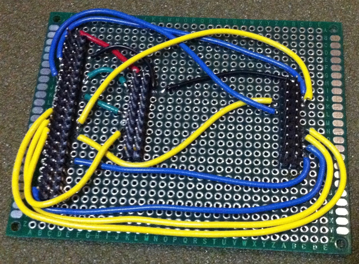
  • I'm happy to report that I built an interface board between my Raspberry Pi 3 and the TDC7201-ZAX-EVM. So far I have only tried reading and writing registers, and bumping the SPI speed up from the RPi default of 0.5 MHz to 16 MHz, but it all works fine so far. This takes the normal 40-wire ribbon cable from the Pi.

    Signals:

    Red: 3.3V

    Black: GND

    Green: ENABLE and OSC_ENABLE (using arbitrary RPi GPIO pins set to output).

    Yellow: SPI (MOSI,MISO,SCLK,CS1,CS2) Note that the SPI pins are hardwired on the RPi, so there's no choice about the pins for these wires.

    Blue: TRIG1, INT1, TRIG2, INT2 (using arbitrary RPi GPIO pins set to input).

    Note that DOUT2 is not hooked up yet. I don't need it to test converter #1, and I'm still uncertain about how the Rpi spidev library handles the chip selects, so I didn't want to short it to DOUT1 without further investigation.

    Also note that I did not add pull-up resistors to CS1 and CS2 yet. That would probably be good engineering practice so they're guaranteed to be high during power up. But with DOUT2 still disconnected, there's no danger.

    If I was doing it over again, I would use a keyed box header for the 2x20 pin RPi header. But this is good enough for bring-up.

    The test software is in Python. I'll put it up on Github after I clean it up a bit. I don't think there's any need to move to C for a speedup, since it's going to be spending most of its time waiting for measurement-complete interrupts anyway.

    One thing that was a little tricky (using the spidev xfer2() function) is that you have to send null padding bytes after your read command to provide time for the returning data to be clocked. For an 8-bit register you need 1 padding byte and the data you want is in position [1] (not [0]) of the vector return value; for 24-bit you have to send 3 padding bytes and the data is in positions [1][2][3]. Other than that it's been pretty easy going.

    I spent some time looking at Arduino too, but the lack of a file system or any real time clock would have meant a lot of extra work to get data logging going. The Raspberry Pi is a Real Computer (TM). :-)