This thread has been locked.

If you have a related question, please click the "Ask a related question" button in the top right corner. The newly created question will be automatically linked to this question.

TDC1000: bandpass filter & cable query

Part Number: TDC1000

My customer is using TDC1000 for & have following observations:

RF1

CF2

1000

56

2843.4940855323

KHZ

RF2

CF3

5000

56

568.6988171065

KHZ

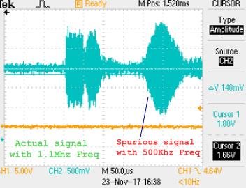
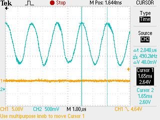
With above settings the second signal is spurious signal with peak voltage more than the actual signal and its frequency is ~500khz.

Peak voltage of the actual signal -- ~-880mv

After that the frequency band is changed as per below

RF1

CF2

2200

56

1292.4973116056

KHZ

RF2

CF3

3300

56

861.6648744037

KHZ

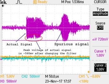
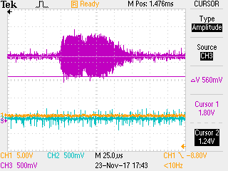
Even with above settings also same problem observed. And also the peal voltage of the actual signal is decreased.

Peak reduced to 560mv from 880mv

Freq of spurious signal ~520 Khz
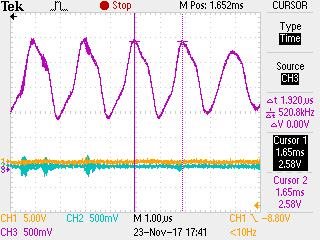
1. Please suggest the band pas filter values / components to have a band of 850Khz to 1.25Mhz.
2. Is there any relation to echo peak voltage and filter band?
3. Please suggest the cable that should be used b/w sensor and the TDC1000, Min cable length reqd: 2.5meters 

  • Hello,

    I will look into this and get back to you.

    Regards,
  • Hi Scott,
    Please help sharing your comments.
  • Hello Prahlad,

    Because of the filter topology, decreasing the width of the passband will also decrease the gain through the passband. The result will be lower output with an only marginally narrower passband. If the most important characteristic is the center frequency, this topology is fine, and I would suggest the following components:

    RF1= 750ohm

    RF2= 7.5kohm

    CF2= 50pF

    CF3= 100pF

    I arrived at these using a TINA simulation that I have attached.1MhzFilter.TSC

    The customer can use this schematic to experiment and model new filters before trying them on the board.

    Preferably the TDC1000 should be relatively close to the transducers. Over that distance there may be noticeable noise depending on the environment. A twisted cable pair would be good, and even better if it is shielded. 

    The spurious signal is something that I have not seen before. If it is truly some external noise source it is not likely ultrasonic but instead is electromagnetic, since the transducer will not function well at that frequency (if this is a 1Mhz transducer).