This thread has been locked.

If you have a related question, please click the "Ask a related question" button in the top right corner. The newly created question will be automatically linked to this question.

TDC1000-GASEVM: Gas purity sensing flow meter giving unexpected ToF values.

Part Number: TDC1000-GASEVM

Hello,

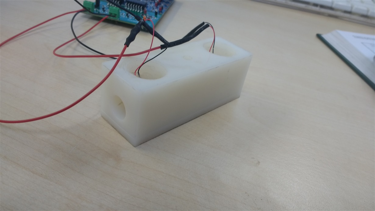
I am trying to use the TDC1000-GASEVM as a flow meter, so that ultimatley I can sense the purity of gas in the flow. Currently I am just using a 3D printed test rig incorperating reflectors (figure 1), and will pass argon through it from a bottle once I can configure the boards to work as I'm expecting, using the GUI supplied by TI.

I would like to make a time of flight measurement in one direction, then swap the transducers' roles and make a time of flight measurement in the other direction, I believed I had set the configuration files correctly, but evidently I am missing something. I get a much shorter time of flight than expected for my path, and curiosly this doesn't appear to change when I disconnect my transucers. I'm not sure what to make of this and am struggling to trouble shoot because I'm not 100% sure that the transducers are functioning as I would like them to.

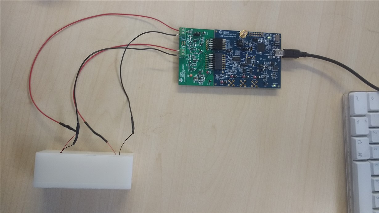
The transducers I am using are 300kHz, connected to the higher voltage booster board (see figure 2), and I have uploaded my coniguration files also. The path fom transducer 1 to transducer 2 is 7.2cm, making the calculated time of flight around 218us and they are connected to the nylon using Loctite 406 with a layer of hot glue on top.

Config files:

17042018_TDC1000_Setup.txt
TDC1000_Config0                         24
TDC1000_Config1                         40
TDC1000_Config2                         12
TDC1000_Config3                         0D
TDC1000_Config4                         5F
TDC1000_TOF-1                           40
TDC1000_TOF-0                           1E
TDC1000_Error_Flags                     00
TDC1000_Timeout                         23
TDC1000_Clock_Rate                      01
TDC1000_Conts_Trigger                   00
TDC7200_Config1                         82
TDC7200_Config2                         40
TDC7200_Interrupt_Status                06
TDC7200_Interrupt_Mask                  07
TDC7200_Coarse_Cntr_Ov_H                FF
TDC7200_Coarse_Cntr_Ov_L                FF
TDC7200_Clock_Cntr_Ov_H                 FF
TDC7200_Clock_Cntr_Ov_L                 FF
TDC7200_Clock_Cntr_Stop_Mask_H          00
TDC7200_Clock_Cntr_Stop_Mask_L          00
TRIGGER_UPDATE_FREQ                     0000
TDC_AVG/STDEV_NUM_ELEMS                 00C8
SAVE_GRAPH_DATA_TO_FILE                 00
FLOW_MODE_SELECT                        00
Y-SCALE_CENTER                          0032
X-SCALE_RANGE                           0032
MEASURE_RTD1                            00
SAVE_RESULT_REGR_TO_FILE                00
GRAPH_MULTI_STOPS                       00
TDC_SELECT                              00
TEMP_RTD_SELECT                         00
TEMP_RTD_MODE                           00
TEMP_AVG/STDEV_NUM_ELEMS                000A
SAVE_TEMP_DATA                          00
GRAPH_YMAX_DATA                         000000000000036A
GRAPH_YMIN_DATA                         0000000000000306
TDC1000-HV_DRV_EN1                      01
TDC1000-HV_DRV_EN2                      01
HV_DRV_EN1_Period                       012C
HV_DRV_EN2_Period                       012C
ENABLE_POWER_CYCLE                      00
CLK_FREQ_(1-16MHz)                      1.200000
CLK_SOURCE_SEL                          02
CPU_CLK_FREQ                            04
CPU_CLK_EN                              01
TDC1000-HV_BST_PWR_EN                   01
HV_BST_PWR_EN_Period                    0000
FWD2REV_FLOW_DELAY                      0000
TDC1000-IMPE_MATCH_EN                   00
ENABLE_UART_STREAM                      00
ENABLE_MSP430TIMER_TDC                  00
17042018_TDC7200_Setup.txt
TDC1000_Config0                         24
TDC1000_Config1                         40
TDC1000_Config2                         11
TDC1000_Config3                         0D
TDC1000_Config4                         5F
TDC1000_TOF-1                           40
TDC1000_TOF-0                           1E
TDC1000_Error_Flags                     00
TDC1000_Timeout                         23
TDC1000_Clock_Rate                      01
TDC1000_Conts_Trigger                   00
TDC7200_Config1                         82
TDC7200_Config2                         40
TDC7200_Interrupt_Status                06
TDC7200_Interrupt_Mask                  07
TDC7200_Coarse_Cntr_Ov_H                FF
TDC7200_Coarse_Cntr_Ov_L                FF
TDC7200_Clock_Cntr_Ov_H                 FF
TDC7200_Clock_Cntr_Ov_L                 FF
TDC7200_Clock_Cntr_Stop_Mask_H          00
TDC7200_Clock_Cntr_Stop_Mask_L          00
TRIGGER_UPDATE_FREQ                     0000
TDC_AVG/STDEV_NUM_ELEMS                 00C8
SAVE_GRAPH_DATA_TO_FILE                 00
FLOW_MODE_SELECT                        00
Y-SCALE_CENTER                          0032
X-SCALE_RANGE                           0032
MEASURE_RTD1                            00
SAVE_RESULT_REGR_TO_FILE                00
GRAPH_MULTI_STOPS                       00
TDC_SELECT                              00
TEMP_RTD_SELECT                         00
TEMP_RTD_MODE                           00
TEMP_AVG/STDEV_NUM_ELEMS                000A
SAVE_TEMP_DATA                          00
GRAPH_YMAX_DATA                         000000000000036A
GRAPH_YMIN_DATA                         0000000000000306
TDC1000-HV_DRV_EN1                      01
TDC1000-HV_DRV_EN2                      01
HV_DRV_EN1_Period                       012C
HV_DRV_EN2_Period                       012C
ENABLE_POWER_CYCLE                      00
CLK_FREQ_(1-16MHz)                      1.200000
CLK_SOURCE_SEL                          02
CPU_CLK_FREQ                            04
CPU_CLK_EN                              01
TDC1000-HV_BST_PWR_EN                   01
HV_BST_PWR_EN_Period                    0000
FWD2REV_FLOW_DELAY                      0000
TDC1000-IMPE_MATCH_EN                   00
ENABLE_UART_STREAM                      00
ENABLE_MSP430TIMER_TDC                  00

Figure 1 (test rig):

Figure 2 (connection to BST board):


  • Hi Archie,

    I would start by decreasing the HV Driver EN period. It looks like you have it set to 300us. It really only needs to be active for as long as the TX pulses are switching. In this case with a 300Khz signal, it should only be about 13us long. Maybe set it to about 15us just to be safe. I also recommend adjusting your blanking period so that it ends just before you expect to receive the signal.

    You can see some explanations of all these settings in the FAQ here: e2e.ti.com/.../3611.everything-you-need-to-know-for-ultrasonic-tof-liquid-coupled-collateral-tools-designs-faq

    Also, for a flow metering application I suggest using single-echo mode instead of multi-echo.

    Regards,
  • Scott,

    thanks for your reply, I've made your changes to no avail, but have noticed something very strange. I disconected the two transducers and found that the data reada did not change, so I'm wondeering if there could be some sort of interference on the board or similar, I cleared the plot and disconnected then reconnected the board to check if it was just a glitch but it was persistant.. I've been through the jumpers, they're all connected and in the correct position (JP6 on cpu, JP5 to 7200 pin).

    I have attatched a screen capture of my plot.

    Figure - Plot: