This thread has been locked.

If you have a related question, please click the "Ask a related question" button in the top right corner. The newly created question will be automatically linked to this question.

TDC1000-GASEVM: configurations tdc-1000-GASEVM

Part Number: TDC1000-GASEVM

Hello!
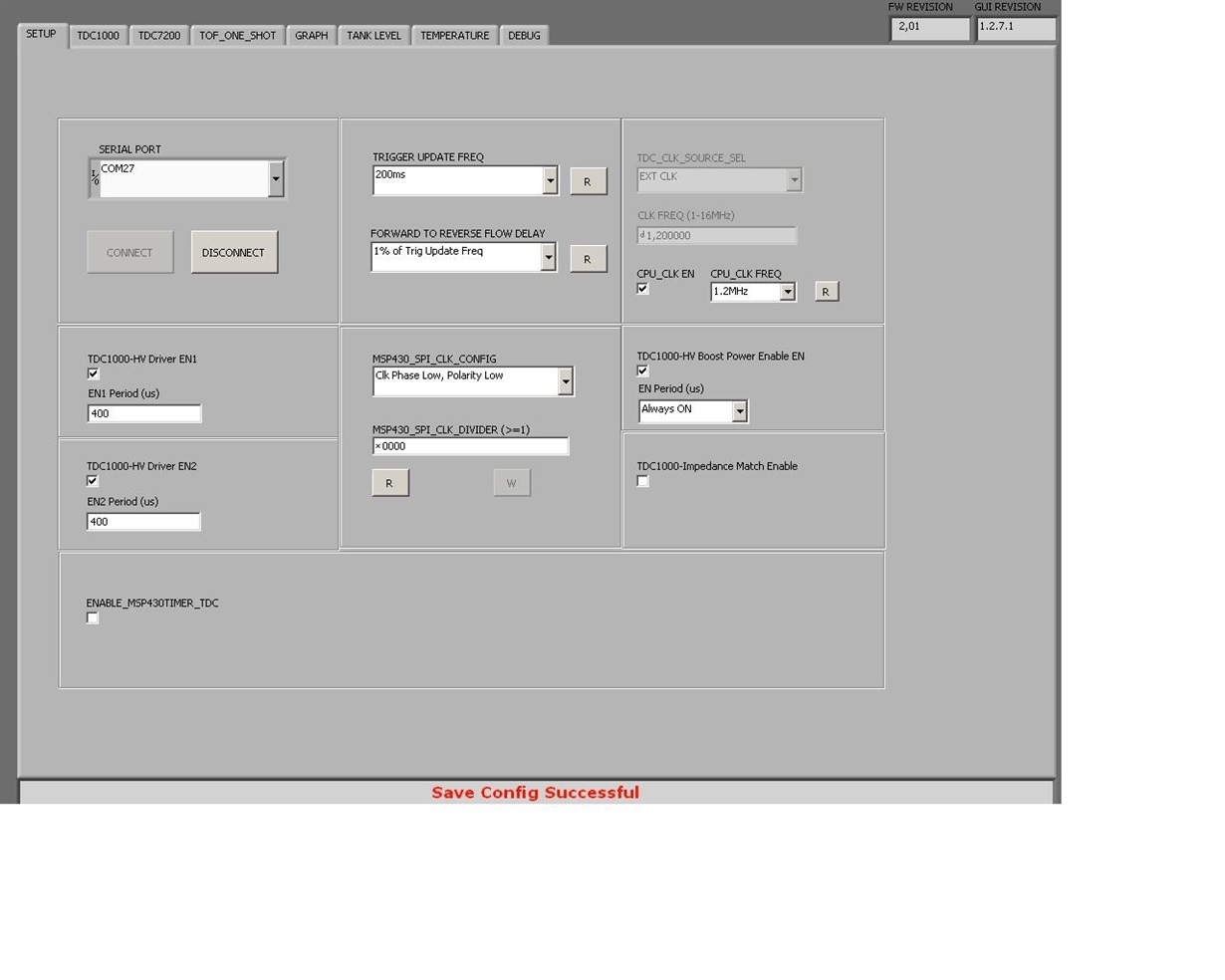
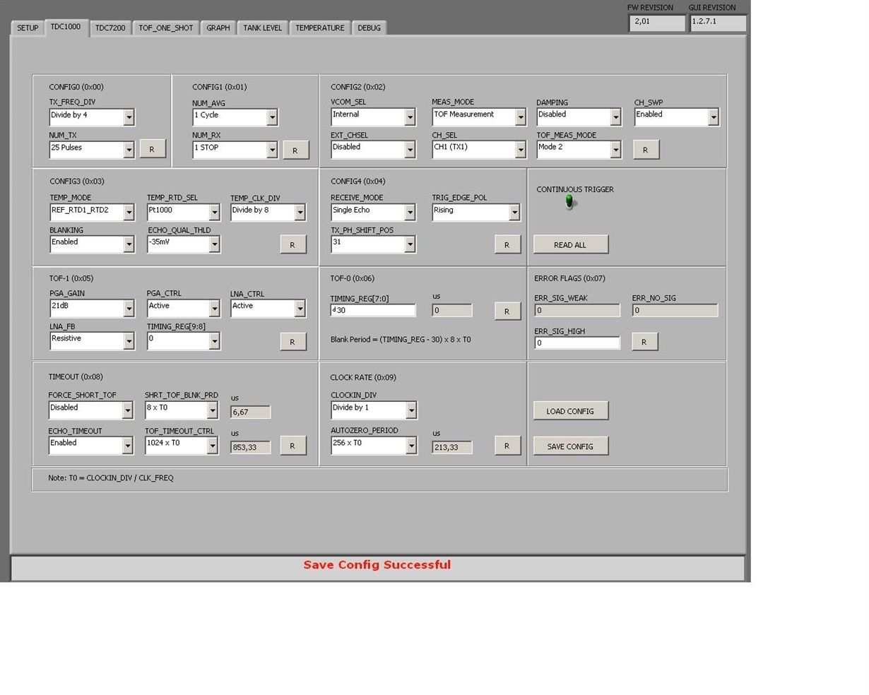
I ask you to help me change the settings so that there is no dedicated peak.
I hope for competent help, thank you in advance!

300kHz_100mm.txt
TDC1000_Config0                         39
TDC1000_Config1                         41
TDC1000_Config2                         12
TDC1000_Config3                         08
TDC1000_Config4                         1F
TDC1000_TOF-1                           E4
TDC1000_TOF-0                           1E
TDC1000_Error_Flags                     00
TDC1000_Timeout                         03
TDC1000_Clock_Rate                      02
TDC1000_Conts_Trigger                   01
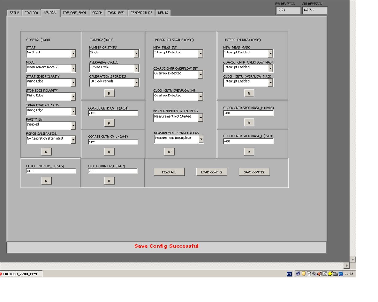
TDC7200_Config1                         02
TDC7200_Config2                         40
TDC7200_Interrupt_Status                07
TDC7200_Interrupt_Mask                  07
TDC7200_Coarse_Cntr_Ov_H                FF
TDC7200_Coarse_Cntr_Ov_L                FF
TDC7200_Clock_Cntr_Ov_H                 FF
TDC7200_Clock_Cntr_Ov_L                 FF
TDC7200_Clock_Cntr_Stop_Mask_H          00
TDC7200_Clock_Cntr_Stop_Mask_L          00
TRIGGER_UPDATE_FREQ                     0001
TDC_AVG/STDEV_NUM_ELEMS                 000A
SAVE_GRAPH_DATA_TO_FILE                 00
FLOW_MODE_SELECT                        01
Y-SCALE_CENTER                          C350
X-SCALE_RANGE                           0032
MEASURE_RTD1                            00
SAVE_RESULT_REGR_TO_FILE                00
GRAPH_MULTI_STOPS                       00
TDC_SELECT                              00
TEMP_RTD_SELECT                         00
TEMP_RTD_MODE                           01
TEMP_AVG/STDEV_NUM_ELEMS                000A
SAVE_TEMP_DATA                          00
GRAPH_YMAX_DATA                         000000008CCCCCCC
GRAPH_YMIN_DATA                         000000007FFFFFFF
TDC1000-HV_DRV_EN1                      01
TDC1000-HV_DRV_EN2                      01
HV_DRV_EN1_Period                       0190
HV_DRV_EN2_Period                       0190
ENABLE_POWER_CYCLE                      00
CLK_FREQ_(1-16MHz)                      1,200000
CLK_SOURCE_SEL                          02
CPU_CLK_FREQ                            04
CPU_CLK_EN                              01
TDC1000-HV_BST_PWR_EN                   01
HV_BST_PWR_EN_Period                    0000
FWD2REV_FLOW_DELAY                      0000
TDC1000-IMPE_MATCH_EN                   00
ENABLE_UART_STREAM                      00
ENABLE_MSP430TIMER_TDC                  00

  • Hello,

    Your HV enable period is quite long given the amount of time it actually takes to transmit your signal. At 300Khz with 25 pulses, it will take a little over 80us to complete the transmission. First, I would set your HV enable period to be about 85-90us instead of 400us. With such a long HV enabled period, you may run into trouble with receiving the return echo.

    Your other configuration settings seem to be fine. I would recommend reading up to 5 stop pulses on the TDC1000 and TDC7200 just so you have more to work with.

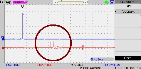
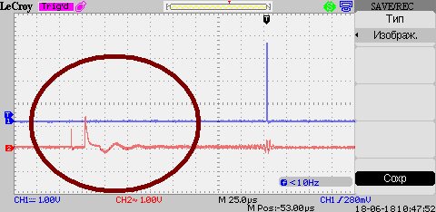
    What are the signals in your scope capture? Is it the START pin and COMPIN? Can you also post the a screen capture that includes the TX pin as well?

    Thanks,
  • Hello! Thank you very much for the detailed answer, but unfortunately the instructions did not help. The signal at the output of TX2 is disproportionately small compared to TX1. I can't understand the nature of the interference before the echo signal and how to deal with it.

  • On my screens depicted START, COMP_IN, STOP.