Other Parts Discussed in Thread: MSP430FR5969
Tool/software: Code Composer Studio
Good morning,
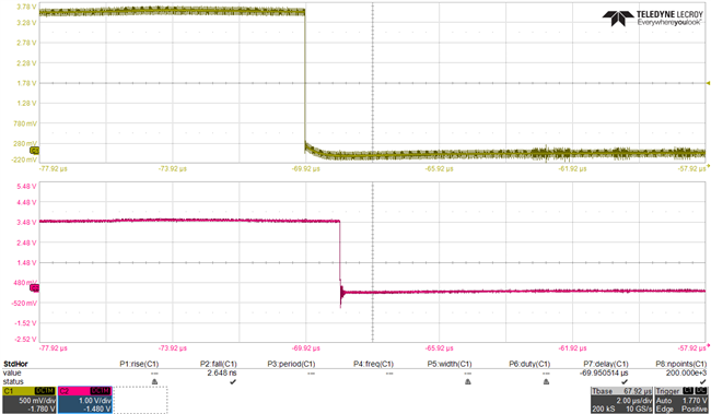
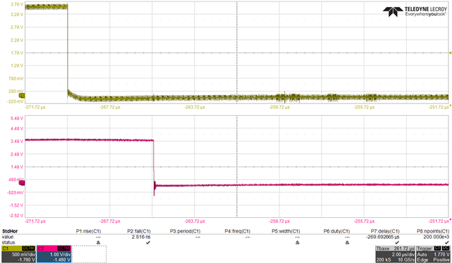
I'm using a TDC7200 to measure the ToF. Up until this moment, I've successfully configured all the registers and I'm able to see the interrupt on INTB pin. The TDC is configured to operate in Mode2 (16MHz external CLOCK), with a single STOP, 2 Calibration cycles at the end and with START, STOP and TRIGG at falling edge. The NEW MEASUREMENT and CLOCK_COUNTER_OVF Interrupts are enabled while the COARSE_COUNTER_OVF is disabled in INT_MASK. I've set the CLOCK_CNTR_OVF to several different values and the interrupt instant on INTB responds accordingly. For e.g., in the images below, I've set the overflow condition to 1us and 4us and one can see the INTB pin (Red signal) switching at the right time after the falling edge on START (yellow). I've also verified the INT_STATUS register after each interrupt and I obtain 0x1D (Clock overflow detected). The problem I'm facing is reading the CLOCK_COUNT1 registers. In principle, I should read the same value set on the CLOCK_CNTR_OVF. Whatsoever, I'm always reading 0.
Can someone please point me out the problem? The code I'm using is also shown below (MSP430FR5969 microcontroller).
Thank you very much,
Joaquim
P.S.- In the meantime, I've done some tests with an external STOP signal and the TDC seems to be unable to detect it and continues to interrupt at the time defined through CLOCK_CNTR_OVF.
#include <msp430fr5969.h>
#define nop __asm__ __volatile__("nop\n\t");

float f_p = 10, duty_cycle = 0.65;                      // Setup PWM parameters for periodic START signal
uint8_t restart[2] = {0b01000000, 0b10111011};          // Set new measurement
int restart_len = sizeof(restart)/sizeof(restart[0]);
uint8_t RX_buffer[3] = {}, aux[3] = {}, aux_2[3] = {};  // Buffers where read values are stored

void setup_PWM(float , float);
void setup_TDC();
void SPI_send(uint8_t *, int);
void SPI_receive(uint8_t *, uint8_t);
void ToF_read();

void setup(){
  PM5CTL0 &= ~LOCKLPM5;

  Serial.begin(115200);    // Set UART to send to Serial Monitor

  P3DIR |= 0x20;           // Output SMCLK @ 16MHz
  P3OUT &= ~0x20;

  P2DIR &= ~0x10;          // Interrupt pin for TDC
  P2REN |= 0x10;
  P2IES |= 0x10;
  P2IFG &= ~0x10;
  P2IE |= 0x10;

  P3DIR |= 0x10;
  P3SEL1 |= 0x10;

  setup_TDC();             // Configure TDCs
  delay(2);

  setup_PWM(f_p,duty_cycle);    // Setup PWM
}


void loop(){
  Serial.println(aux[0]);     // Print CONFIG1 after Interrupt (in decimal)
  Serial.println(RX_buffer[0]);   // Print 3 bytes read from CLOCK_COUNT1
  Serial.println(aux_2[0]);   // Print INT_STATUS after Interrupt (in decimal)
  Serial.println(RX_buffer[1]);
  Serial.println(RX_buffer[2]);
}

#pragma vector=PORT2_VECTOR
__interrupt void PORT2_ISR_HOOK(void){
  ToF_read();                                                       // Read data
  P2IFG &= ~0x10;
  P2IE |= 0x10;                                                     // Re-enable Interrupt
}

void setup_PWM(float f_pwm, float dc_pwm) {
  P1DIR |= 0x04;                                                    // P1.2 as the PWM output (dedicated pin)
  P1OUT &= ~0x04;
  P1SEL0 |= 0x04;

  TA1CTL |= TASSEL_2 | ID__1 | MC_1 | TACLR;
  TA1CCTL1 = OUTMOD_7;
  int T_0 = int(16000 / f_pwm);
  int T_1 = int(dc_pwm * T_0);
  TA1CCR0 = T_0;
  TA1CCR1 = T_1;
}

void setup_TDC(){
  // SPI configuration
  P3DIR |= 0x01;    // CS pins (active-low)
  P3OUT |= 0x01;
  P1DIR |= 0x10;
  P1OUT |= 0x10;

  UCB0CTLW0 = UCSWRST | UCSSEL_2;
  UCB0CTLW0 |= UCCKPH | UCMSB | UCSYNC | UCMST;
  UCB0CTLW0 &= ~UCCKPL;
  P1DIR &= ~0b10000000;
  P1DIR |= 0b01000000;
  P1SEL1 |= 0b11000000;
  P1SEL0 &= ~0b11000000;
  P2DIR |= 0b00000100;
  P2SEL1 |= 0b0000100;
  P2SEL0 &= ~0b00000100;
  UCB0BR0 = 1;      // 16 MHz SPI CLK
  UCB0BR1 = 0;
  UCB0CTLW0 &= ~UCSWRST;

  // Configuration registers
  uint8_t CONFIG1[2] = {0b01000000, 0b10111011};      // Start New measurement | Mode 2 | START, STOP, TRIGG falling edge | Force CAL | No parity
  uint8_t CONFIG2[2] = {0b01000001, 0b00000000};      // Single stop | No averaging | 2 CAL cycles
  uint8_t INT_MASK[2] = {0b01000011, 0b00000101};     // Enable New measurement and Clock counter overflow enabled (Coarse counter overflow disabled)
  uint8_t CLOCK_CNTR_OVF_H[2] = {0b01000110, 0b00000000};   // Overflow set @ 1us for 16MHz external clock
  uint8_t CLOCK_CNTR_OVF_L[2] = {0b01000111, 0b00010000};
  uint8_t CLOCK_CNTR_MASK_L[] = {0b00000000, 0b00000000};   // No STOP mask

  int config_len = sizeof(CONFIG1)/sizeof(CONFIG1[0]);

  SPI_send(CONFIG2,config_len);
  SPI_send(INT_MASK,config_len);
  SPI_send(CLOCK_CNTR_OVF_H,config_len);
  SPI_send(CLOCK_CNTR_OVF_L,config_len);
  SPI_send(CLOCK_CNTR_MASK_L,config_len);
  SPI_send(CONFIG1,config_len);
}

void ToF_read(){                  // Read data from TDC whenever INTB interrupts
  SPI_receive(RX_buffer,0x11);    // Read CLOCK_COUNT1
  SPI_receive(aux,0x00);          // Read CONFIG1 after measurement
  SPI_receive(aux_2,0x02);        // Read INT_STATUS

  SPI_send(restart,restart_len);  // Set New measurement bit in CONFIG1
}

void SPI_send(uint8_t *data, int len) {
  P3OUT &= ~0x01;     // CS low
  while (len){
    while(!(UCB0IFG & UCTXIFG));
    UCB0TXBUF = *(data++);
    while(!(UCB0IFG & UCTXIFG));
    UCB0TXBUF = *(data++);
    while (UCB0STAT & UCBUSY);
    len-=2;
  }
  P3OUT |= 0x01;      // CS high
}

void SPI_receive(uint8_t *buffer, uint8_t addr){
  P3OUT &= ~0x01;
  while(!(UCB0IFG & UCTXIFG));
  UCB0TXBUF = addr;   // Address of register to read

  while(!(UCB0IFG & UCTXIFG));
  UCB0TXBUF = 0x00;
  while (UCB0STAT & UCBUSY);
  buffer[0] = UCB0RXBUF;

  while(!(UCB0IFG & UCTXIFG));
  UCB0TXBUF = 0x00;
  while (UCB0STAT & UCBUSY);
  buffer[1] = UCB0RXBUF;

  while(!(UCB0IFG & UCTXIFG));
  UCB0TXBUF = 0x00;
  while (UCB0STAT & UCBUSY);
  buffer[2] = UCB0RXBUF;

  while (UCB0STAT & UCBUSY);
  P3OUT |= 0x01;
}


