This thread has been locked.

If you have a related question, please click the "Ask a related question" button in the top right corner. The newly created question will be automatically linked to this question.

AWR1642BOOST: Understanding changes in "TX start time" and "ADC valid start time"

Part Number: AWR1642BOOST
Other Parts Discussed in Thread: MMWAVE-DFP

Hello;

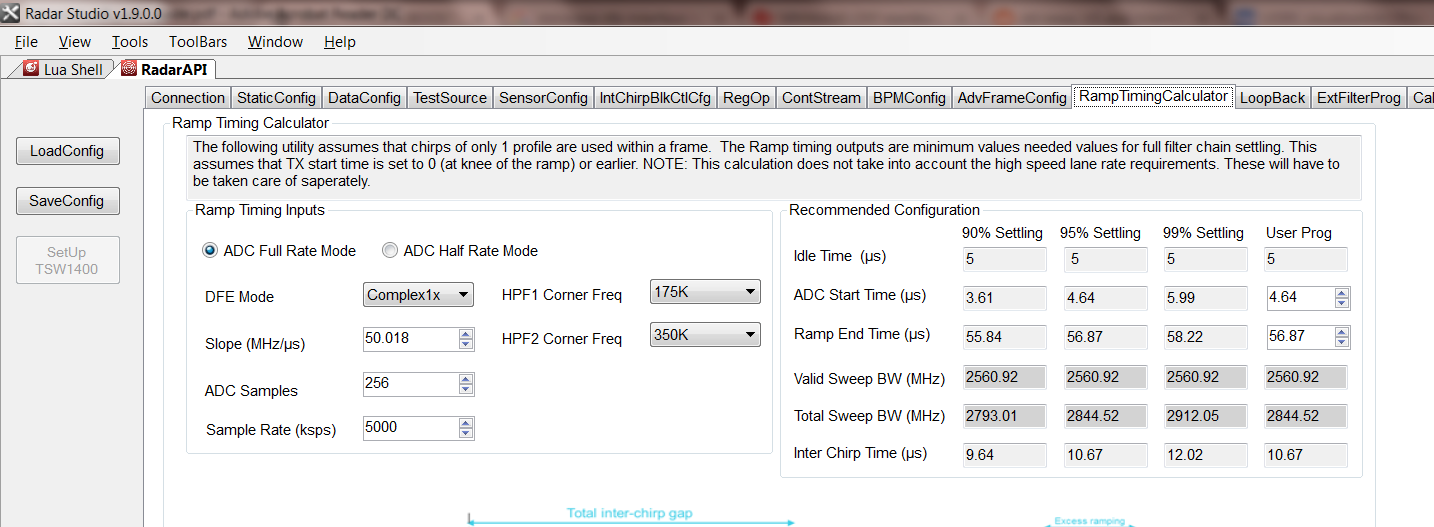
I have two questions related to the profile configuration of a chirp.

According to mmwave_sdk_user_guide.pdf Figure 2: Chirp Diagram, the TX start time entered into the profile configuration should turn on the transmitter X us BEFORE the ramp start. Based on my observations, it appears to be doing the opposite of that and turning the transmitter on x us AFTER the start of the ramp. See images below of collected raw ADC data in an Anechoic environment:

Second, comparing two ramps, one with x us ramp time and one with ~2*x us ramp time, why does the ADC valid start time need to be increased to avoid collecting transient data? Below is raw data of a ramp of 18us compared to a 38.5us ramp, both using a 7us ADC valid start time until ADC data is collected. The 18us does not have any transient at the beginning, whereas the 38.5us has an additional 5-10 samples of poor data. Why do I need to wait longer before collecting valid data from longer ramps? Is this transient a function of the sampling frequency and not simply time?

I'm trying to understand this so I can dynamically calculate profile configurations while guaranteeing that transients are not collected.

Thank you,

Erik

  • Hi Erik,

    This is a very good question, I've referred your ticket to an AWR member who should have an answer for you sometime next week.


    Akash
  • Hi Erik,

    The diagram that you referred to is a bit confusing, and we will try and have it updated. As far as the Tx start time is concerned, it can be a positive or negative number (please see the interface control document from the DFP package www.ti.com/tool/mmwave-dfp).

    All values of the tx start time are relative to the 'knee of the ramp' (where the ramp starts).

    If the tx start time is positive, the tx start is delayed w.r.t the knee of the ramp.

    If the tx start time is positive, the tx starts before the knee of the ramp.

    Regarding your second question, there is a ramp-timing calculator available in the 'RadarStudio' tool from the DFP package that should aid you in avoiding the settling region of the adc. The sampling rate, the ADC mode, the slope of the ramp all affect the amount of settling that is seen in a chirp. 

    Regards

    Anil

  • Anil;

    Thank you, this is helpful.

    Could you please clarify your quote below; you accidentally used the word "positive" twice.

    Anil Mani said:

    If the tx start time is positive, the tx start is delayed w.r.t the knee of the ramp.

    If the tx start time is positive, the tx starts before the knee of the ramp.

    As an FYI, the mmw_demo project casts txStartTime as an unsigned integer before configuring the profile; that's what was confusing me here. 

    profileCfg.txStartTime           = (uint32_t)((float)atof (argv[9]) * 1000 / 10);

    Thanks again,

    Erik

  • Hi Erik,

    Apologies. I made a typo. The correction is as follows.

    If the tx start time is positive, the tx start is delayed w.r.t the knee of the ramp.

    If the tx start time is negative, the tx starts before the knee of the ramp.

    Also, thank you for pointing out the issue in the SDK. We will fix it for the next release. Meanwhile all you have to do is change the uint32_t to an int32_t.

    Regards
    Anil
  • Anil;

    Thank you for your help.

    FYI, it should be cast to a "rlInt16_t"

    Thanks again,

    Erik