This thread has been locked.

If you have a related question, please click the "Ask a related question" button in the top right corner. The newly created question will be automatically linked to this question.

IWR1443: Custom PCB help!

Part Number: IWR1443
Other Parts Discussed in Thread: UNIFLASH, IWR1642,

Hello,

I have created a custom PCB that utilizes the IWR1443 sensor for level sensing application.  So far, I am able to flash the highAccuracy lab demo to the external flash memory (part# MX25R1635FZNIH0) via UniFlash.  Using the CLI commands I am able to execute all of the commands and receive acknowledgement as shown below.  However, when I send the command to start the sensor, it fails.   Can someone help be start the debug process?  I have had two different errors pop up in the Uart output and you can see the CLI commands I am sending below.  I'm hoping that someone has run into this same error while developing and point me in the right direction.  Thanks!


******************************************

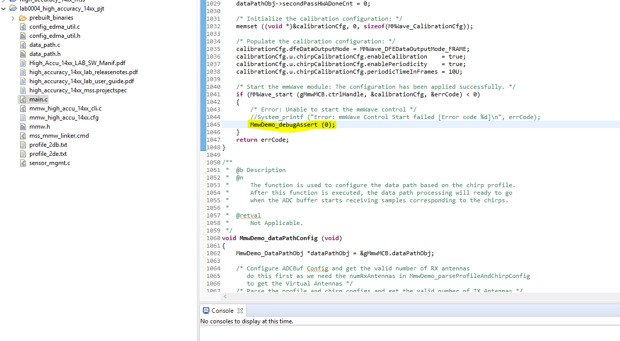
xWR14xx MMW Demo 01.01.00.02

******************************************

mmwDemo:/>sensorStop
Done

mmwDemo:/>
mmwDemo:/>flushCfg
Done

mmwDemo:/>
mmwDemo:/>dfeDataOutputMode 1
Done

mmwDemo:/>
mmwDemo:/>channelCfg 1 1 0
Done

mmwDemo:/>
mmwDemo:/>adcCfg 2 1
Done

mmwDemo:/>
mmwDemo:/>adcbufCfg 0 1 0 1
Done

mmwDemo:/>
mmwDemo:/>profileCfg 0 77 7 7 130.05 0 0  27.96 1 512 4195 0 0 36
Done

mmwDemo:/>
mmwDemo:/>chirpCfg 0 0 0 0 0 0 0 1
Done

mmwDemo:/>
mmwDemo:/>frameCfg 0 0 1 0 500 1 0
Done

mmwDemo:/>
mmwDemo:/>calibDcRangeSig 0 -5 5 32
Done

mmwDemo:/>
mmwDemo:/>guiMonitor 1   1 0  0 0  1
Done

mmwDemo:/>
mmwDemo:/>sensorStart
Debug: Init Calibration Status = 0x5fe

Exception: ../main.c, line 1045.

******************************************

xWR14xx MMW Demo 01.01.00.02

******************************************

mmwDemo:/>
mmwDemo:/>
mmwDemo:/>sensorStop
Done

mmwDemo:/>
mmwDemo:/>flushCfg
Done

mmwDemo:/>
mmwDemo:/>dfeDataOutputMode 1
Done

mmwDemo:/>
mmwDemo:/>channelCfg 1 1 0
Done

mmwDemo:/>
mmwDemo:/>adcCfg 2 1
Done

mmwDemo:/>
mmwDemo:/>adcbufCfg 0 1 0 1
Done

mmwDemo:/>
mmwDemo:/>profileCfg 0 77 7 7 130.05 0 0  27.96 1 512 4195 0 0 36
Done

mmwDemo:/>
mmwDemo:/>chirpCfg 0 0 0 0 0 0 0 1
Done

mmwDemo:/>
mmwDemo:/>frameCfg 0 0 1 0 500 1 0
Done

mmwDemo:/>
mmwDemo:/>calibDcRangeSig 0 -5 5 32
Done

mmwDemo:/>
mmwDemo:/>guiMonitor 1   1 0  0 0  1
Done

mmwDemo:/>
mmwDemo:/>sensorStart
Exception: ../main.c, line 1200.

  • Hello,

       Flashing seemed to work

       Looking at the boot process, you are able to send Control UART messages, and receive status.   

       The MSS Data logger requires us to get Radar data (not tested yet)

        There is a hardware checklist and debug Spreadsheet, it is a board bringup process.

        a) assume you have measured the power supply value, and ripple and noise - they are within the datasheet limits

        b) assume you have used a high impedance oscilloscope and measured CLKP - 40Mhz with proper jitter, ~1v peaktopeak

        c) please make sure the internal power rails 1v4_APLL, 1v4_SYNTH, 1v0_RF_PA, after nRESET = 1 are nominal values.

        d) make sure the Tx and Rx antennas pass a microscope inspection, no solder mask on the RF traces.

        e) If you download the mmwave Studio software package, in the docs folder is an ICD document, it has more information on some error codes

             and internal software functions we send commands from external to MSS.  The MSS reformats these messages for the RF subsystem, and sends them to

              the BSS

        1) in your first example "

    Debug: Init Calibration Status = 0x5fe"
    The BSS processors performed a calibration, and returned the status.

    For IWr1443, the normal calibration status is

    mmwDemo:/>sensorStart
    Debug: Init Calibration Status = 0x7fe

    Done

    The Interface Control Document - 5.2.9, the bit mask of tests

    bits 12 .. 4 are active tests.

    Each of the tests, can be enabled or disabled.

    If you go through a device reset, and program with the OOB demo, and visualizer, the terminal window, 

    if the internal calibration continues to fail, this would be internal to the device.   You need to see if you have a repetitive error.

    you would reflow or replace the part.  The calibration does not use the antenna, it has internal loopback.  

    If you use the Visualizer - OOB first, and you get the RF calibration Done, you 

    can do an antenna test/ range test.  

    The antenna pattern test, azimuth and elevation, can be checked by recording the Visualizer response, or

    using CCS capture the L3 memory, for the receiver data, or 1D FFT data.

    In My opinion,the High Accuracy demo, is more difficult to do device bringup, TIDEP91 Level sensing, also has simpler signal processing

    but uses SPI instead of UART.  

    You should always reset the device between attempts to reprogram, for debugging.

    Regards

    Joe Quintal


  • Radio Joe,

    Thanks for your suggestions. I am going to build up a couple more devices just to try to rule out any soldering issues and then perform the tests you recommend. This is the first time dealing with BGA packaging for me so soldering mistakes are probably somewhat likely. Where are the temperature sensors used within the system? There are two sensors that are connected via the I2C bus. Are these used in the calibration process? Can someone describe how and where they are used in the code?

    Cheers!
  • The I2C temperature sensors are not required for calibration. They are for external temperature monitoring . The device has internal temperature sensors for calibration.

    They are not in the active code, there are examples under the mmwave driver software.

    Regards
    Joe QUintal
  • Is the AR_NRST signal controlled by the XDS110 for starting the sensor? In other words is there a certain timing sequence of the Radar's Reset pin being pulled low to high when you need to start or initialize the sensor. I ask because that is the only signal I do not have connected between my radar board and the XDS110 on the eval module.

    Thanks!
  • Hello,

    In the CCS if we need to assert a hardware reset, the initial EVM has a parallel path of AR_nRESET, AR_NRST_XDS,  AR_MCU_nRST, and Manual Reset pushbutton.  If you can attache to the ARM R4F processor with the XDS110 Debug probe, you don't need it.

    In the other application of Uniflash, you can manually use the  manual RESET pushbutton.

    There is a power on sequence for the sensor in FIgure 5-2 in the datasheet.  Hold nRESET = 0, all power supplies in range, wait at least 1ms,

    release nRESET.

    See attached figure.

    Regards.

    Joe Quintal

    mmwave_figure5p2.pdf

  • Hi Joe,

    Thanks for all of your efforts in clarifying everything!  So the problem I am facing may be  due to not incorporating the the PMIC into our design.   I noticed today that the PMIC is controlled by the IWR1443 sensor itself over I2C bus.  Can you describe briefly the functions the PMIC performs in the overall system of the EVM?  My design only provides the power rails needed without the PMIC.  Can you explain briefly the need of the PMIC in the overall design or point me to some documentation.  By not having it, can the sensor still initialize and pass calibration state?  Is it critical for proper sensor operation? 

    With my power supply I did as the checklist suggested and determined that when the reset signal drops below 2V that the power rails still persist.  Also all of the voltages are within spec as far as accuracy and ripple.   I'm becoming convinced that I need to start the design process over by following the design checklist that I failed to use the first go around.  However, I'm hopeful to find the current issue before I start a new design.  Thanks! 

    -Jason

  • Hi Jason,
    If you control the power sequence, or have a monitor, then the PMIC is not required, although its suggested.

    Figure 5-2 in the datasheet, shows that you bring all 4 power rails to the value, and 1-3ms later you release the nRESET signal.
    If you monitor the WARM_RESET (with pullup) you will see that after the nRESET 0->1 the Warm Reset goes to 0, and then after the SOC
    init its a '1'.

    The PMIC I2C is not used in the base design.

    Key points, are nRESET 0->1 (check the voltage low is < .3v)
    a) SOP pins need to be stable before nRESET 0->1 (proper code)
    b) VBGAP 0.9v
    c) 1v4_APLL, 1v4_SYNTH 1.4v
    d) VOUT_PA 1.0v
    e) CLKP (DVM to GND) .5v
    f) CLKM (DVM to GND) .5v
    g) CLKP, CLKM - 40Mhz ~1vptp

    h) load QSPI, eventually using a terminal with the OOB demo loaded - you will see a set of terminal messages on the Control UART Tx

    If you turn off the Serial TeraTerm, you can attach with the Visualizer, and download a simple IWR1443, 1Tx, 1Rx example for Best Range,
    Select the Displays for Noise and Magnitude only

    i) when you send the commands, there is a large change in the 1.8v, and 1.3v current. In the original EVM this is why there are LDOs.
    There are very sensitive ripple and noise specs for 1.8 and 1.3v (see datasheet).

    j) looking at the Visualizer terminal screen after Sensor Start, there is a Calibration Status 0x7fe, and Done, the device should be chirping.
    If the code is not 0x7fe, it could be soldering, it could be the antenna 50 ohm connections. it could be the power, or it could be a bad part.
    Check the above on a TI EVM and do comparitive troubleshooting.

    Good Luck,
    Joe QUintal
  • Hello Joe,

    Can the reset signal be released (-> 1) any time after the power rails are up?  Say 2 seconds after?  The way I read the data sheet is that it doesn't matter when you allow the reset signal to go high on power up, as long as the voltage rails are up?

    Also, could my device be failing at the point of "SensorStart" CLI because it can not communicate with the PMIC?  Recall I don't have one in my design.

    I have assembled 4 devices and still only one device can I get to flash with uniflash.  The other devices just get stuck here as shown in the image.  This couldn't be a boot loader issue right?   

    Thanks again!

  • Hello,

    The nRESET needs to be '0' until 3ms after power is OK.  Anytime later than that nRESET can be a '1'.

    The SOP pins determine the boot mode,  you want SOP2.0 101 for flashing, 001 for Functional.

    These pins have to be in the proper state also when nRESET changes from 0->1 (we latch the state for the boot rom)

    The PMIC is not required to have I2C, if PMIC_EN (GPIO1 is '1') the PMIC should sequence, you can look at PGOOD, it is low until 6ms after

    the 3.3v is stable.  It requires a pullup.

    0702.mmwave_figure5p2.pdf

    Problem set 1)  fails to boot (follow attached figure)

     a) use an oscilloscope - trigger on nRESET 0->1, measure WARM_RESET (requires pullup), QSPI_CSn(functional SOP)

     -  nRESET should remain high with no glitches after start of boot.

     -  WARM RESET goes from 1->0 at  nRESET 0->1, it is low for the Radar HW Init time, when it 0->1 we start booting

     -  VBGAP should be .9v after nRESET 0->1 (can also be a 1.2 or 1.8v power problem)

     -  1v4_APLL, 1v4_SYNTH should be 1.4v after VBGAP is .9v

     -  1v_PA_OUT, should be 1v after 1v4_SYNTH  is 1.4v.

     -  CLKP, CLKM with DVM should be .5v after VBGAP is .9v

     -  CLKP, CLKM with high impedance scope probe should be 40Mhz 1vptp

     -  make sure you followed the pullups for NERRORin, NERRORout, WARM_RESET

     - make sure you followed the pullups for QSPI interface, QSPI_CS, QSPI[D3.D0] , QSPI_CK ser term

      At this point if you have copied the XDS110 TIVA processor design - you need to flash it over USB

     or

      Once the XDS110 debug probe is attached to your passive header (sprui94.pdf)

           GND

           Control_UART_Tx (UART Rx on XDS110)

           Control_UART_Rx (UART Tx on XDS110)

           MSS Logger_UART_Tx (UART Aux Rx on XDS110)

            XDS_nRESET - with puliup

            TMS - with pulldown

             TDI -

             TDO -  (part of SOP logic - copy interface)

             TCK - pulldown, series term

      place the SOP pins [2.0] as 011 - no boot

       depress the local RESET pushbutton

       try to JTAG attach to the R4F processor

       (you could write a program over CCS to take the place of Uniflash - I don't have one (check E2E)

         once that works, we should be able to look at Uniflash SOP[2.0] 101

         depress reset pb then release

    Try to connect with Uniflash, follow both the Uniflash and mmwave SDK User Guide to flash the Out of Box demo.

    Stop Uniflash, move SOP jumper [2.0] to 001

    Turn on board, depress reset, under Control panel find Control port #

          check PC for Control UART

    Open a terminal emulator for the Control Port, set serial port

    depress the reset button to check the Control UART output.

    At this point you can close the terminal emulator and continue to the visualizer to down load code, and run an application.

    2) Calibration failure - if the calibration value after RFInit is not 0x7fe, there is a device failure, device to board failure, or a power failure.

    if the device is a IWR1642 ES2 or IWR1443 ES3 device, you need to have the proper BSS patch.

    You can recompile the OOB demo, so that your calibration status is OK, by not running that test with the calibration setup mask

    (ie if your OOB calibration status is 0x5fe, you could recompile the code to only perform the 0x5fe bit mask).  the radar may not work properly,

    but if the bit mask is the same after calibration the software should allow RF Chirp.

    3) please try simple range tests first.   There are a lot of visualizer features, we first need to check the Field of View in Azimuth for 1Tx and 4Rx.

    use a water bottle (full of water) at elevation centerline, take a piece of string from the antenna centerline, and mark off the same distance (radius) with 

    mark spacings of 15 degrees (180/n * pi*r), the visualizer should be able to track your distance (2-3 meters) within the azimuth resolution (30 degrees) by moving the water bottle.

    Repeat the Tx1, Rx[4.1] test for other azimuth antennas (like Tx3)

    Elevation.. to be continued..

    Regards,

    Joe Quintal


  • Joe,

    Again thanks for your most detailed response!  I will proceed with your checklist today but I thought I would run this by you.   On the one device of my own design that I had uploading the bin files to flash, I should have mentioned that I had actually had swapped the flash memory from the EVM that I received from TI (PN: S25FL116K0XNFV01) with the new one I ordered from digikey (PN: MX25R1635FZNIH0) . 

    The digikey part worked perfectly on the TI 1443 BOOST EVM  so I figured I had found a compatible flash chip.  However, on my circuit boards I can only get a binary to load to flash if Iuse the orignal Spansion flash chip that came with the EVM. 

    Can you think of why the EVM would be more acceptable to different flash memory chips?  Bootloader?  SPI Traces? 

    Thanks! 

  • Hello
    There are specific pullups and series resistors on the IWR1443 EVM. Please make sure you copied those.
    A difference for layout with ES2 vs ES3 IWR1443 is that QSPI speed increases from 18 to 40Mhz. Make sure you matching is OK.
    QSPI design rules are to match all 6 traces (although the CS could be slightly off).

    The ES2 part only supports specific QSPI flash, see the IWR1443 Errata document. Next month you can order the IWR1443ES3 part,
    it supports more flash devices, and the boot time is faster, BSS code is in ROM, 40Mhz QSPI.

    Also tomorrow, the TI web WR1443 RevB Altium package will be included with the Cadence package if that helps. Look under the IWR1443BOOST EVM Technical documents

    Regards,
    Joe Quintal
  • Joe,

    We have got JTAG working properly and we are uploading bin files through CCS.  However, we are still seeing similar error codes such as 0x1fe after calling the "sensorStart" command.  

    We  ran the OOB demo with mmWave sdk V1.2 and watched the console output in the online visualizer and this was the output:

    mmwDemo:/>% ***************************************************************
    Skipped
    
    mmwDemo:/>% Created for SDK ver:01.02
    Skipped
    
    mmwDemo:/>% Created using Visualizer ver:2.0.0.2
    Skipped
    
    mmwDemo:/>% Frequency:77
    Skipped
    
    mmwDemo:/>% Platform:xWR14xx
    Skipped
    
    mmwDemo:/>% Scene Classifier:best_range_res
    Skipped
    
    mmwDemo:/>% Azimuth Resolution(deg):15
    Skipped
    
    mmwDemo:/>% Range Resolution(m):0.044
    Skipped
    
    mmwDemo:/>% Maximum unambiguous Range(m):9.01
    Skipped
    
    mmwDemo:/>% Maximum Radial Velocity(m/s):1
    Skipped
    
    mmwDemo:/>% Radial velocity resolution(m/s):0.13
    Skipped
    
    mmwDemo:/>% Frame Duration(msec):100
    Skipped
    
    mmwDemo:/>% Range Detection Threshold (dB):15
    Skipped
    
    mmwDemo:/>% Range Peak Grouping:enabled
    Skipped
    
    mmwDemo:/>% Doppler Peak Grouping:enabled
    Skipped
    
    mmwDemo:/>% Static clutter removal:disabled
    Skipped
    
    mmwDemo:/>% ***************************************************************
    Skipped
    
    mmwDemo:/>sensorStop
    Done
    
    mmwDemo:/>flushCfg
    Done
    
    mmwDemo:/>dfeDataOutputMode 1
    Done
    
    mmwDemo:/>channelCfg 15 5 0
    Done
    
    mmwDemo:/>adcCfg 2 1
    Done
    
    mmwDemo:/>adcbufCfg 0 1 0 1
    Done
    
    mmwDemo:/>profileCfg 0 77 429 7 57.14 0 0 70 1 240 4884 0 0 30
    Done
    
    mmwDemo:/>chirpCfg 0 0 0 0 0 0 0 1
    Done
    
    mmwDemo:/>chirpCfg 1 1 0 0 0 0 0 4
    Done
    
    mmwDemo:/>frameCfg 0 1 16 0 100 1 0
    Done
    
    mmwDemo:/>lowPower 0 0
    Done
    
    mmwDemo:/>guiMonitor 1 1 0 0 0 1
    Done
    
    mmwDemo:/>cfarCfg 0 2 8 4 3 0 1280
    Done
    
    mmwDemo:/>peakGrouping 1 1 1 1 229
    Done
    
    mmwDemo:/>multiObjBeamForming 1 0.5
    Done
    
    mmwDemo:/>clutterRemoval 0
    Done
    
    mmwDemo:/>calibDcRangeSig 0 -5 8 256
    Done
    
    mmwDemo:/>compRangeBiasAndRxChanPhase 0.0 1 0 1 0 1 0 1 0 1 0 1 0 1 0 1 0 1 0 1 0 1 0 1 0
    Done
    
    mmwDemo:/>measureRangeBiasAndRxChanPhase 0 1.5 0.2
    Done
    
    mmwDemo:/>CQRxSatMonitor 0 3 5 123 0
    Done
    
    mmwDemo:/>CQSigImgMonitor 0 119 4
    Done
    
    mmwDemo:/>analogMonitor 1 1
    Done
    
    mmwDemo:/>sensorStart
    Debug: Init Calibration Status = 0x1fe
    
    Exception: ../main.c, line 1671.

    "if the device is a IWR1642 ES2 or IWR1443 ES3 device, you need to have the proper BSS patch." 

    I have uploaded the radarss.bin file found in the mmWaveSDK  1.2.0.5.  As far as the silicon version, I am still unsure of how to determine.  I assume it's rev 2?   

    I ordered them on 8/19/2018 from the TI store and the part number is XI1443QGABL-Single-Chip 76-to-81GHz mmWave Sensor Integrating MCU and Hardware Accelerator.

    At this point I am leaning towards something seriously wrong with my board design and I'm willing to try editing the calibration mask bits to try to force the sensor to start chirping.  Perhaps it might lead to another clue?   Can you tell me where I would edit the calibration mask in the OOB demo?

    Thanks again Joe!  


  • Hello,

    You want to use mmwace SDK ver mmwave_sdk_01_02_00_05.  You want to use the IWR1443 software, that has both a BSS download, and and MSS download.

    BSS - C:\ti\mmwave_sdk_01_02_00_05\firmware\radarss\ xwr12xx_xwr14xx_radarss.bin

    MSS - C:\ti\mmwave_sdk_01_02_00_05\packages\ti\demo\xwr14xx\mmw\xwr14xx_mmw_demo_mss.bin

    For the Out of Box demo.  There is also a data capture example using the UART, this is in the software development section.

    If there is a code error, or calibration error, you need to follow through the software function called in the source code, or main, and look at the line number.

    The current IWR1443 part should be ES2.  this requires 2 separate uniflash files, BSS, and MSS.

    The current IWR1642 part should be ES2, however you provide a special combined software image of BSS patch, and MSS and DSS code.

    In the  IWr1443 datasheet Identification section it shows the JTAG ID for electronic signature.

    If you have calibration errors, double check XRAY mounting, coplanartiy, check LDO supplies per the table in the datasheet for noise.

    If you just get calibration errors, if you recompile and force some of the test bit flags to zero, you might be able to pass less tests.

    This is described more completely, by downloading the Radar Studio dfp tool, in the docs folder is an Interface Control Document.

    Regards,

    Joe Quintal

  • Joe,

    We have traced it down to few lines of code.  It is not the same error code or exception in the code every time.  I have traced one error down to "CPU Failure" along with general ones that don't really indicate what the problem is.  Now that we are this far along and I have a semi-consistent hardware stack, I will try a few more radar assemblies and see if I can get one to pass startup tests.  I think I have about 5 assemblies that I can get consistent results out of.  

    I'm hoping that now that we at least have JTAG and some better debugging tools I can figure out what exactly is causing the failure. 

    Do you think it could me timing issues with QSPI signals?  I know they are not matched exactly. I figure the fact that we are flashing bin files to flash, we are ok with the QSPI signals?  Could that cause a calibration error?   

    Some major differences that would effect impedance of antenna traces and maybe other timing issues:

    • Our board is 4 layer vs 6
    • I inadvertently put solder mask over the antenna traces BUT not actual antenna  array.
    • No blind vias were used.  All vias are from top layer to bottom.

    Possible soldering issues.

    • I have a few in-pad vias that are not plated.  In other words, they are pads that have holes in them.  On some of the PCB's I have pre-filled the vias with solder and some I have not.  Some PCBs I have applied solder paste with a stencil, some I have applied tacky flux only.  I believe that pre-filling the via holes and and following up with flux only soldering should result in the correct solder job.

    I will follow up with some screen shots or even some eagle cad files and see if we can get to the bottom of this.  We do not have the resources for Xray inspection locally but perhaps I need to find someone that can help us with that.   

    Again, I'm hoping that now that we can read registers and debug with JTAG we can find the root cause. 

    We are using the most current mmWave SDK 1.2.0.5 code. 

    I will defienlty look at the JTAG electronic signature section in the data sheet  to double check that we are on ES2.

    We owe you one!.   

    -Jason


  • I just wanted to share my design files in case anyone is willing to provide input on the design.  I truly appreciate any help.

    Regards,

    -Jason

    IWRR1443_TankGauge.brdIWRR1443_TankGauge.sch

  • Joe,

    Where would I edit the calibration bit mask in the code?  I haven't been able to find any details on the calibration process.  Can you share any details on what tasks are performed in the calibration process when starting the sensor?  I'd like to setup a breakpoint and step into the calibration portion of the code and maybe see if there are any clues but I'm not sure where to set my breakpoint.  

    Thanks

  • Hello
    Currently you would need to customize the out of box demo. Look for MMWave_openLink() in mmwave_link.c.
    in future mmwave_sdk version 3.0 it can be adjusted. Currently you would have to modify the code to try other than 0x7fe as a mask.
    REgards,
    Joe Quintal
  • Joe,

    I can't find "MMWave_openLink" or the mmwaveLink.c file anywhere in the OOB demo? Can you be more specific on where this is located?

    Thanks!
  • I found it. C:\ti\mmwave_sdk_01_02_00_05\packages\ti\control\mmwave\src\mmwave_link.c
  • Hello Jason,
    "file:///C:/ti/mmwave_sdk_01_02_00_05/packages/ti/control/mmwave/docs/doxygen/html/mmwave__link_8c.html"
    Find this define #define MMWAVE_INIT_CALIB_SUCCESS 0x17FEU
    Change it to your return code.
    It should unblock your test.
    (remember to change it back)
    Regards,
    Joe Quintal
  • Joe,

    Thanks.  The device is chirping and I am able to run the OOB demo and view plots in the Visualizer.  However, it appears as you suspected, that the radar is not working quite right.   It looks like a lot of noise on the plots and doesn't seem able to detect objects very well.    The Doppler seems to work OK but the sensor detects too many objects.  

    I thought it was kind of odd but I can hear a subtle audible chirping coming from the sensor after It starts.   You have to listen close but it's there.  There is no way I'm hearing chirps in the 77GHz range but I am hearing a chirping sound about 10 times a second?  Does this mean anything to you?

    Anyway, from here is there any more clues to my apparent hardware problem that I can get through JTAG / Software Debugging?

    Correct me if I'm wrong please, but I believe that if the sensor is running and logging data to visualizers I have pretty much ruled out the following?

    • QSPI Traces and Timing issues
    • Flash Memory Issues
    • Pullups and Startup Timing

    I have attached a couple images of my visualizer config and plots.

    Thanks again!


  • Hello,
    If the OOB loads, QSPI is OK.
    If the visualizer works without errors, the Control UART, MSS Logger UART and XDS110 are OK.
    If you have attached with CCS to R4F and done some tracing, JTAG is OK.

    You have a higher near DC peak than signal peak, this can be adding the DC Cancellation from Table 1 of the mmwave SDK User Guide, to your Visualizer cfg and sending that information. Also this can be a sign of high leakage from Tx to Rx, you need to characterize your antenna patterns to each patch . The normal antenna is 120 deg azimuth by 40 deg elevation. You can create a crude turntable, with protractor and board mount to an RCS target, use aluminum metal paint on a ping pong ball. Suspended from some out of view support.

    You can see the radiation pattern simulations in the mmwave BOOST EVM User Guide.

    In your layout, you need to retrace the Power and GND layers, GND has VSSA and RF return for L2. There are special holes on L2 under the Tx and Rx RF pads. There are RF stiching vias from L1 to L2 that are filled. Some of these connect to L4, L6.

    The main device has VSS L4,L6 GND, some thermal vias. The VSSA mostly connects to L2, some to L2 and L6.

    The PMIC is not returned to L2, this is important to switching noise. Please check the PMIC and RFLDO Grounding, follow the device datasheets and the EVM layout.

    Try to get 2 boards to this level, then check the 1v3, 1v8 power meets the specification. The mmwave sensor has specific Power supply rejection requirements. Adding second stage LC filters (actually just the 2nd ferrite bead) before the RFLDO may help if its too noisy).

    The hum is from the PMIC output caps, or the PMIC. The Switching frequency is 2, 4Mhz. There are different style power inductors for SMT that can be used (H frame) Murata parts, that can minimize this. Some people like their power supplies to sing a little (joke).

    get your second board to this level, then try measure/optimize the power, and characterize the antenna radiation pattern.
    The calibration error code, if its the same for both boards leads to the device mounting, power, GNDing. The calibration error code
    does not include the antenna.

    Regards.
    Joe Quintal
  • Joe,

    Is the complete Cadence / Allegro project available for us anywhere to download?  It would sure make my life easier to download the project and fork it to meet our requirements.  Can someone provide that for us?   

    Thanks for the last response.  I do have two boards at the same state.  It is interesting to know that the antenna traces have nothing to do with the calibration.   I think I just totally underestimated the impedance control importance in this design and deviated too far from the reference design. 

    Thanks.

  • Hello,
    The antenna traces do not affect calibration, they do affect antenna radiation pattern and extra close in reflections. This is why measuring the antenna radiation pattern with a known target, angle (rotate the board on a pedastal - leave the target in a fixed place), turn the board 90 degrees for elevation.

    If you get the same calibration code on both boards, send it back, I will ask the designers for a guess. Is your code still 0x5fe?

    The entire project has been updated to both Cadence, and Altium under the mmwave IWR1443 BOOST technical documents - look at this link under design files " www.ti.com/.../iwr1443boost "
    Regards,
    Joe Quintal
  • Joe,

    I keep getting an 0x3FE back on the two boards.

    Thanks!
  • Joe,

    We are having a hard time opening the schematic in those design files in OrCad. It seems like the library dependencies are not there? I'm not really familiar with the Cadence PCB design tools. My friend is asking if you have a CIS version of the schematic rather than the HDL version in the files. Do you know how to open this project in OrCad so we can start editing the design files?

    Thanks

  • Hello,
    I don't have conversion software. I only have the HDL version. I have seen for Cadence to OrCad, there is a converter listed under the Cadence E2E. The Altium lists a converter to OrCAD on the Altium website.

    I don't use Orcad. Sorry
    Joe Quintal