This thread has been locked.

If you have a related question, please click the "Ask a related question" button in the top right corner. The newly created question will be automatically linked to this question.

AWR1642BOOST: Question about Decoder in the Binary Phase Modulation

Part Number: AWR1642BOOST

Hello

Is the documentation promoted in this thread now available?:

 https://e2e.ti.com/support/sensors/f/1023/t/603800 

I understand the Binary Phase modulation, but I have doubts about where the decoder should be placed.

You mention the text below In this link: http://www.ti.com/lit/an/swra554a/swra554a.pdf 

The processing chain is almost identical to the flow as described earlier in the context of TDM-MIMO, with
the exception of a decoding block which enables the signal contributions from the individual TX antennas
to be separated in the received data. This decoding must be performed before the angle-FFT (and ideally
after the Doppler-FFT, in order to enable phase corrections due to non-zero velocity to be applied prior to
decoding).

Does this mean that the doppler FFT would take as input a distorted version (Hadamard combination of the Txs) of the FMCW signal? Why is it not possible to decode immediately after the ADC?

Thanks for your help

Hector Gonzalez

  • Hello Hector,

    I think BPM removal can be done directly on ADC data. It could be just design choice to use the optimal processing chain on HWA or DSP. Let me get back to you with more details on this.

    Regards,
    Kaushal
  • Hello, thanks for your prompt response, I will wait for your details. The only reason that I could think about it for placing it after the Doppler FFT is to use the Doppler map as a way of separation, but the CDMA approach is not really a frequency division method, so I am a little bit confused with your suggestion for the location of the decoder. For me it needs to be placed immediately after the ADC, holding the previous signals with shifting registers until they are all available to perform the decoding process.

    Thanks

    Hector G

  • Hi Hector,

    The ADC passes through FFT's (range and Doppler). Since both the FFT and the decoding processes are linear operations, their order can be interchanged without distorting the final decoded result.

    The recommended order is the following:
    (a) perform the range and Doppler FFT,
    (b) then perform a phase-compensation to compensate for target motion
    (c) perform decoding (Sa+Sb)/2, (Sa-Sb)/2

    This allows us to correctly compensate for the phase that is induced due to relative target motion prior to decoding. [If the target is moving, then there will be a relative phase between the received signal arising from the transmission of the first chirp (S1+S2), and the received signal arising from the transmission of the second chirp (S1-S2).] Performing the Doppler-FFT decomposes the signal into different doppler-bins, which allows this motion induced phase compensation to be performed correctly.

    IF THERE WHERE NO RELATIVE MOTION, then decoding could be performed either on the ADC data, after the range-FFT, or after the doppler-FFT. Linearity would ensure that the final result is right.

    Sandeep
  • Hello Sandeep

    First of all, thank you very much for your prompt response. 

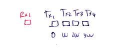
    I am trying to make sense of the recommended order that you suggested, and I have some questions about it. Please refer to the next plot to clearly show them to you for one receiver and two transmitters:

    Questions:

    1. Do you need to apply the sum of the Tx signals to the mixer how it is shown in the picture above? Or do you need an independent mixer for each transmitted signal?

    2. If you apply the sum of the signals to the mixer, do you compensate for the phase difference induced by the spacing of the TXs? Depending on the TX arrangements, there will be a small delay introduced by the angle of departure of the signal just how it is shown below (Which is the phase difference used to increase the resolution to two virtual channels with an additional phase difference):

    3. After you apply the Range-Doppler FFT. How do you physically achieve compensation at this point? The whole point of the Doppler FFT is to use that phase difference that you want to compensate across chirps to get the velocity of the object. Do you remove this phase difference? If you remove it, how are you still able to get the velocity of the object? I believe the concept of the signals Sa and Sb is lost at this moment. The only data available is arranged in a Range-Doppler matrix, where the rows are range indexes and the columns contain a velocity scale.

    4. After the recommended phase compensation, you reach the decoder. If you have mixed everything and only have a Range-Doppler frame, How do you know at the decoder what is the contribution coming from Sa and Sb?

    5. How do you physically extract two frames (Those associated with the virtual channels) out of one frame (The one obtained through the range doppler FFT).

    6. If you perform the decoding of the signal after the Range-Doppler FFT, it means you cannot compress the range FFT results, because  you need the complete information to recover the signals. Am I correct? This might result in a poor hardware implementation because a huge amount of data needs to be held.

    I understand your point about the phase induced by the movement of the object, which is a high contaminant for the decoder of the signal. Because the S1 (Or S2) embedded in the Sa would be different to the S1 (Or S2) embedded in the Sb second transmission. However, it is not clear for me how the Range-Doppler FFT could be useful to identify this phase physically in such a way that it could be useful for the decoder. 

    Thank you very much for your kind help, and please apologize me if I have mentioned anything inappropriate.

    Hector Gonzalez

  • Hello Sandeep

    I want to apologize for the previous long question, but I am doing my best to understand the BPM mode, so that I can take the most out of my AWR1642Boost. I have reduced my doubts up to only this one:

    For a Binary Phase Modulation scenario with 4 TXs and a single receiver:

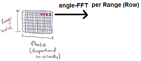
    Assuming we go through the regular processing (LNA, Mixing with the 4 signals, Amp, LPF, FFT1 across fast time, FFT2 across chirps) and we obtain the next range-doppler map:

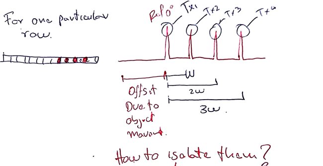
    Which contains a phase deviation due to the velocity of the object W_v. For one fixed range (Fixed row), we observe four peaks in the 2nd FFT phases, which are the contributions coming from Tx1, Tx2, Tx3 and Tx4. I understand what you meant about the phase compensation using W_v to obtain a clear contribution from each of them because there is an offset introduced by W_v:

    What I don't understand is how to isolate them. You mentioned in your post to use the decoder formula at this point for Sa, Sb, Sc and Sd, but for me the concept of signal per chirp is lost at this point. My question is How this separation (Or decoding) is achieved at this point?

    Thank you very much in advance for your help.

    Hector G

  • Hi Hector,

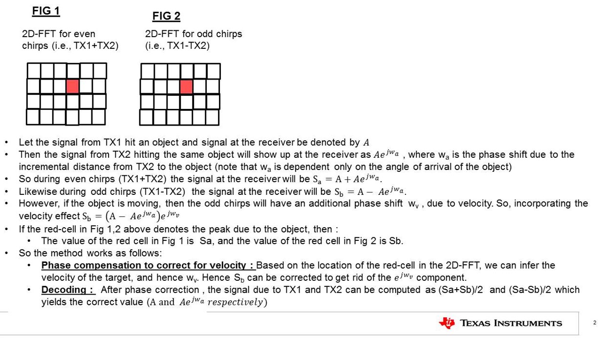
        (a) One thing that is perhaps not clear in the app-note is that the  2D-FFT is done separately for odd chirps (TX1+TX2) and even chirps (TX1-TX2).

    So at every RX antenna,  we perform two 2D-FFT's : one for the even chirps and one for the odd chirps. See the explanation in the diagram below which is the processing done at a single RX antenna.. 

    (b) In the diagram, it is important to note that the peak (red cell) will occur at the same location in both the 2D-FFT's (Fig 1 and 2), though with a different phase.  

    Let me know if this clarifies your question.

    Sandeep

  • Hello Sandeep

    First of all thank you very much again for your prompt response. It is such an honor for me to receive a direct explanation from you.

    The detail of having an additional FFT for the odd transmission clarifies the separation. However, I have two small questions out of your reply:

    1. It is true that the velocity will not affect the first "even" transmission (Tx1+Tx2), but in a long sequence of chirps (192 for example), is it correct to affirm that all the "even" chirps will not be affected by the velocity? I think all chirps after the first one, "odd" or "even", will have the phase shift due to the velocity because the object will not stop moving at any moment. Could you please tell me if I'm wrong?

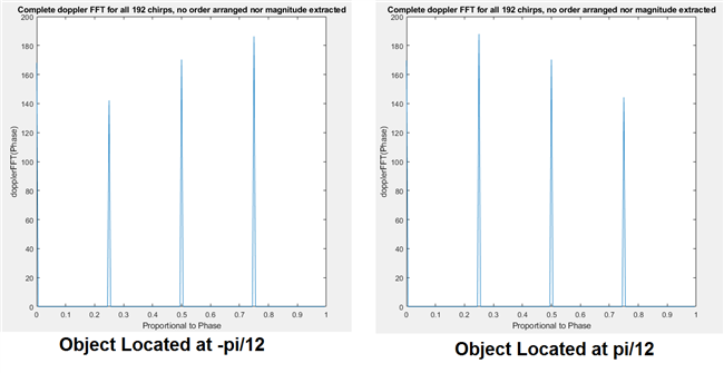
    2. At the end of the day, I was thinking that the separation (Decoding) itself is not needed to extract content from the virtual channels. Because after the phase compensation, the simultaneous peaks (Or red points) in the same range row (Of the same 2D-FFT matrix) allow a direct application of the angle-FFT for the estimation of the angle-of-arrival without losing any resolution.

    Below, the left graph shows an example for a static object located at an angle = -pi/12, and the right graph contains the same object located at an angle pi/12. In both cases, the application of the angle-FFT within the same Range Row would give the direction of arrival. Please tell me if there is any major reason to not skip the decoding.

    Thank you very much for your help. It has been truly significant.

    Hector G

  • Hi Hector,

    1) You are right : every chirp will have a velocity induced phase offset compared to the first chirp. So each subsequent even chirp will have a phase offset of 2wv compared to the previous even chirp. Like wise with the odd chirps.  However, these odd and even sequences get collapsed into a single peak after the Doppler-FFT.

    2) The decoding stage allows you to separate the contributions of TX1 and TX2 to each of the 4 RXS. After decoding you would have  a sequence of 8 virtual antennas. The angle induced phase will increase linearly across all these 8 antennas. So you get  8 antennas instead of 4 antennas ,=> which improves the quality of angle estimation.

  • Thank you Sandeep, it is pretty clear now.

    Hector G