This thread has been locked.

If you have a related question, please click the "Ask a related question" button in the top right corner. The newly created question will be automatically linked to this question.

PGA460: Can the asynchronous UART command of pga460 be used in synchronous UART mode?

Part Number: PGA460
Other Parts Discussed in Thread: , TDC1011

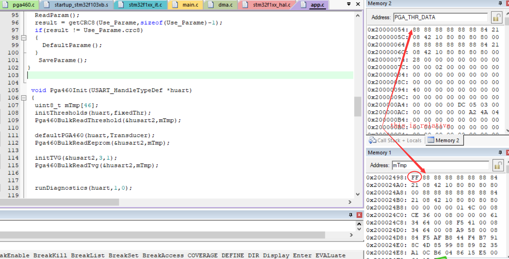
It is normal for me to use the asynchronous serial port for control on pga460. Now I need to read data through the synchronous UART in test mode. Can the commands similar to the storage of eeprom in the asynchronous mode also be used in the synchronous mode?

  • Hi Jiahao

    It is possible to use PGA460 is synchronous mode using RXD, TXD and SCLK pins. Please see section 7.3.6.2.1.8 of datasheet. Commands that are available in asynchronous UART mode will also work for UART synchronous mode.

    Regards,

    Vaibhav
  • Hi Jiahao

    Did the previous reply resolve your query? If not, please give more specific details about your question so that we can help better.

    Regards,

    Vaibhav
  • hi vaibhav,

    Thank you for getting back. I  have used the uart interface to pga460  and the program have been debug success. Now , I change the interface from uart to usart. then the error is appear.

    when i do "threshold bulk read" cmd after "thresholk bulk write" cmd,the data of read is shift a byte. so the other cmd like "eeprom bulk write"and "eeprom bulk read" and ohters.

    Here's another question, at the datasheet of pga460,the usart is LSB(the 8 bit is b0,b1,b2,b3,b4,b5,b6,b7),but in my system the data be tested is MSB(b7,b6,b5,b4,b3,b2,b1,b0).why?

    how they communication?

    why i can read data from pga460 if the communication format is no compatibility?

  • The program can control the pga460 output the ultrasound ,but the wave is not my except. I don't know if the value written into eeprom is right
  • Hi Jiahao,

    It seems like you have a USART read issue.

    You say that you can control the PGA460, which means that your write works fine, but it seems like the data read is not working.

    Can you read a register with a good known value and confirm that your read works?

    When you say that the wave is not acceptable, what do you mean? Are you trying to use the "Direct Data Burst through USART" mode?

    Regards,

    Viktor.

  • dear viktor,

    I want to use USART  control the pga460, and try to use the "Direct Data burst throuth USART".

    I have made this test like the below picture : set a special value at the USER_DATA areo, write and read back, the 0x55 aa 66 99 is the good value, but the first value 0xFF is wronge value.

    the code is this :

    void Pga460BulkReadEeprom(USART_HandleTypeDef *huart,uint8_t *pData)
    {
    uint8_t EEP_BUFF[3] = {syncByte,EEBR,calcChecksum(EEBR)};
    HAL_USART_Transmit(huart, EEP_BUFF,3,5);
    HAL_USART_Receive(huart,pData,46,5);
    }

    it is error return code which read signal register.

    uint8_t i= 0;
    uint8_t Buff1[4] = {0x55,0x09};
    // offset : 00h~2Bh
    for(i=0;i<0x2C;i++)
    {
    regAddr = i;
    Buff1[2] = regAddr;
    Buff1[3] = calcChecksum(9);
    HAL_USART_Transmit(huart, Buff1,4,5);
    HAL_USART_Receive(huart,Buff1,3,5);
    *pBuf++ == Buff1[1];
    }

    it is same to set pga460 work mode,the code is below:

    void Pga460SetMode( USART_HandleTypeDef *huart,uint32_t mMode )
    {
    uint8_t mTmp[5] = {syncByte,0x0A,0x4B};

    regAddr = 0x4B;
    switch ( mMode )
    {
    case PGA_DP_DISABLE :
    // normal
    regData = PGA_DP_DISABLE;
    break;
    case PGA_DP_LPF:
    // lpf output
    regData = PGA_DP_LPF;
    break;
    case PGA_DP_RECTIFIER:
    // rectifier output
    regData = PGA_DP_RECTIFIER;
    break;
    case PGA_DP_BPF:
    // bpf output
    regData = PGA_DP_BPF;
    break;
    case PGA_DP_ADC:
    // adc output
    regData = PGA_DP_ADC;
    break;
    default:
    break;
    }
    mTmp[3] = regData;
    mTmp[4] = calcChecksum(0x0A);
    HAL_USART_Transmit(huart, mTmp,5,5);

    mTmp[1] = 0x09;
    mTmp[2] = 0x4B;
    mTmp[3] = calcChecksum(0x09);
    HAL_USART_Transmit(huart, mTmp,4,5);
    HAL_USART_Receive(huart,mTmp,3,5);         -----the return value is not writed by code

    }

  • Dear viktor,

    Does the register programming of eeprom require unlocking every time, like signal write EE_CNTRL?
  • Hi Jiahao,

    It is important to note that when the device first powers-on, the EEPROM memory is read/loaded into a volatile shadow register memory space. The device then refers to the values in the shadow registers for active operation. Every read and write command accesses the shadow register space, not EEPROM memory directly. It is only necessary to program the EEPROM when you want to save the shadow register configuration directly to EEPROM so that when you power-cycle, these shadow registers will have been retained in EEPROM. The EEPROM programming sequence described in section "7.6.1 EEPROM Programming" of the datasheet refers to this direct EEPROM update process. During evaluation, you do not need to program the EEPROM every time you change the shadow register value for the changes to take effect.

    Here is some clarification regarding the PGA460’s direct-data burst synchronous output mode:

    The synchronous mode requires the use of TXD, RXD, and SCLK. There is no chip/slave select on the PGA460 as typically found on SPI devices, which is why synchronous UART is only SPI-like. However, a SPI port can still be used; simply float the chip select from the MCU. Unlike the asynchronous mode, no start or stop bits are required in the synchronous mode. The synchronous transmitted data would be identical to that of the asynchronous mode, but without the start/stop/inter-byte-space bits.

    For example, sending a Preset 2 Burst+Listen command to detect 4 objects using the PGA460 assigned with UART_ADDR=1, you’d send a continuously clocked synchronous sequence of {0x55,0x21,0x04,0xFA}, which is (from left to right) the sync field, addr-command byte (preset 2 burst-and-listen command to address ‘1’), command data byte0 (number of objects to detect is 4), and checksum.

     Here is a USART sequence example to use the direct data burst mode preset 2 burst-and-listen command:

    In this example, the UART_ADDR=0(default) and the number of object is ‘1’, although the number of objects does not matter since the ADC output does not provide the threshold comparator output. As long as the number of objects is valid (1-8 objects), the burst/listen command will execute for the direct data mode.

    1)      Master initiates standard synchronous mode USART command at 8MHz clock rate:

    PGA460 Pin

    Hex Sequence

    RXD

    {0x55,0x01, 0x01, 0xFD}

    TXD

    Idle at 0xFF

    SCLK

    8MHz active


    2)      Here is where the direct data burst differs from a typical burst-and-listen command. In a typical burst/listen command, the master can stop sending a clock, and simply wait for the record length to expire until reading back the ultrasonic measurement results. However, in the synchronous mode, the master continues to transmit an active 8MHz clock immediately after the burst/listen command. The MOSI should output an idle high value of 0xFF:

    PGA460 Pin

    Hex Sequence

    RXD

    {0xFF…0xFF}

    TXD

    Idle at 0xFF

    SCLK

    8MHz active


    3)      The PGA460 will not start to return ADC data on MISO until after ~120us from the time of sending the burst-and/or-listen command.

    PGA460 Pin

    Hex Sequence

    RXD

    {0xFF…0xFF}

    TXD

    ADC data out

    SCLK

    8MHz active


    4)      It is important to continuously keep the clock active and transmit an idle high 0xFF to the PGA460’s RXD pin. However, for preset record lengths above 12ms, I advise that you occasionally send a non-0xFF to prevent the PGA460’s USART port from timing out. I.e. MOSI transmit 0xC3 every 10ms. Otherwise, the PGA460 will cease to output ADC data after approximately ~15ms.

    PGA460 Pin

    Hex Sequence

    RXD

    {0xFF…0xFF, 0xC3, 0xFF…0xFF, 0xC3, 0xFF }

    TXD

    ADC data out

    SCLK

    8MHz active


    Here is a close-up of the initial USART direct data mode command sequence to show the ADC output delay  between the burst/listen command and TXD output.

    Note: MOSI = PGA460_RXD, MISO = PGA460_TXD, SCLK=PGA460_SCLK.


    The logical bit length at 8Mbps is the maximum supported rate for the synchronous mode.

    To configure your master’s SPI port for synchronous UART mode, the PGA460 requires:

    • Least Significant bit first
    • 8 bits per transfer
    • SPI_Mode2
      • Clock is high when inactive (CPOL=1)
      • Data is valid on clock leading edge (CPHA=0)
      • Enable line is active low (PGA460 does not use the slave/chip/enable select, but it may help for debug and logic analyzer use)

    This is described in the datasheet as “In this mode the USART interface acts as a serial-shift register with data set on the rising edge of the clock and sampled on the falling edge of the clock.”


    To evaluate and get the raw ADC or DSP data using the PGA460-Q1 EVM and GUI, follow these steps:

    1) Select Data Monitor from the tree list.

    2) Click the Graph sub tab.

    3) Select the Graph Mode (ADC or DSP) for 1MSPS output.

    4) Before clicking START, select Test Mode from the tree list

    5) You can increase the amplitude resolution from 8 bit (default) to 12 bit on the Test Mode tree list Data-Path Sample Select radio.

    Note: if you leave the resolution at 8bit, then the digital multiplier determines which 8-bits of the ADC/DSP output are captured.


    6) Return the Data Monitor, and click Run.

    7) You can export the graph data just like the Echo Data Dump data from the Export sub tab

    8) Click Export Last Data Dump to save graph data as a txt or csv file.


    Note: when the record length is very long, it may take a few seconds for the graph to update.

  • Dear Akeem,

           Thanks for your reply. Through your method, I have obtained the corresponding data on the evaluation board and carried out the algorithm evaluation on the original data.

            Now i  am designing a distance measurement system to use pga460. Because the max distance is 10 meter, so the result of pga460 output is not meet requirement.  I want to read the AFE data from pga460 and analysis the data.At first, the MCU I chose was STM32F103, but now it turns out that the computing power of this chip may not be enough.It is found in the literature of ti that tms32f280x series +tdc1011 is used. Could you recommend an MCU of tms320f28 series to replace it?

  • Hi Jiahao,
    I suggest that you post this questions about the MCU replacement on the MCU E2E forum. They will be able to provide you with a better recommendation based on your processing and memory requirements.