This thread has been locked.

If you have a related question, please click the "Ask a related question" button in the top right corner. The newly created question will be automatically linked to this question.

FDC2112: the result is false

Part Number: FDC2112

Hello;

I use FDC2112 to measure capacitor with single ended mode. I read data from fdc and calculate frequency value. Also I measure frequency value with scope.

The frequency value is equal to each other. But when I convert to capacitor to frequency value, the cap value is wrong.

I use 22pF, 33pF, 47pF and 100pF ceramic capacitor for this test. In adition I measure this capacitor with LCR meter to lear exact value.

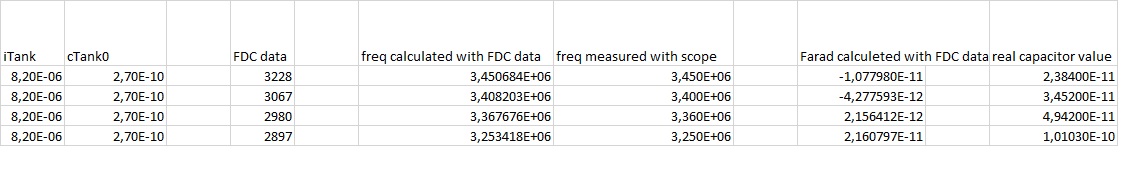
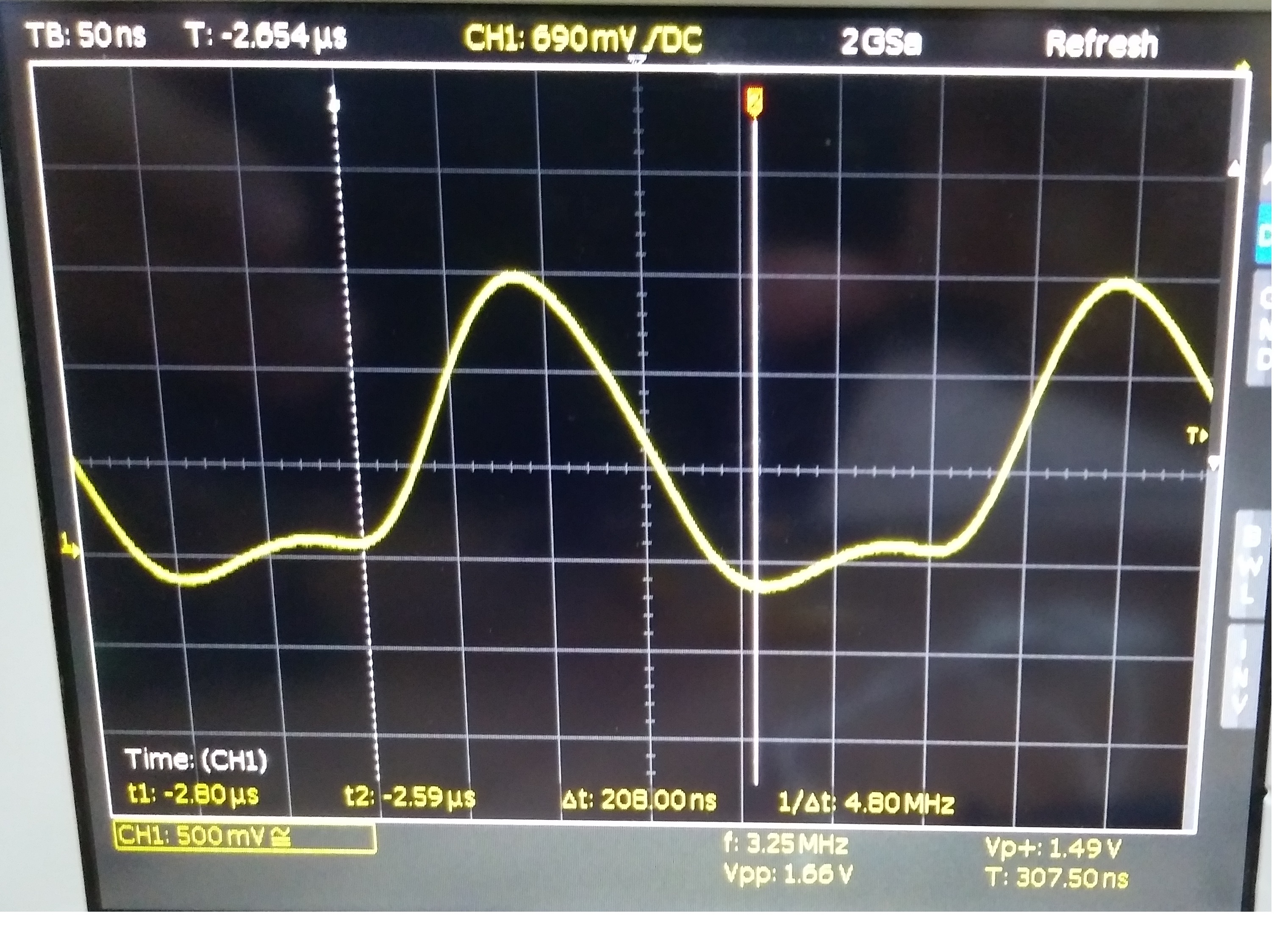
As you see all value is up. But calculated value with FDC data is wrong. You may see an scope screen below.

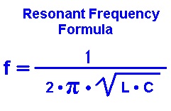
When I  use to calculate above formula all result is wrong. It looks like tank capacitor change with frequency.

Please help.

Best Regards.

  • As a result the FDC count frequency right. I think problem is LC circuit. Resonant frequency effect of some sort of thing.

    When I add difference capacitor to the circuit, the frequency changes is not proportional.

    What is reason of this effect.

    What can i do eleminate to disturbance effect.
  • Hi Jack,
    We've got your request. Allow us some time to test this out and get back to you.

    Best Regards,
    Bala Ravi
  • Hi Jack,
    This could be because of parasitic capacitance. Can you re-run this test without a cap, and measure the cap value? This will be your parasitic capacitance and you can add this to the actual cap value that's being used to get to the desired value. Finally, we also have an useful tool: "Inductive Sensing Design Calculator Tool", which you can download from here: www.ti.com/.../slyc137. I hope this helps!

    Best Regards,
    Bala Ravi
  • Hi Bala;

    Firstly, I measure parasitic capacitance, as related on datasheet, Also you wrote above.

    Then to find real capacitance value, parasitic capacitance substructed from measured fdc value.
    Of course all conversion which are data to capacitance, have done before substraction.

    The above test also made this method.

    But the measurement is false.

    Best Regards.
  • Hi Bala;

    I have done same test again as you wish.

    data         Measured Capacitance                 real value

    3230          0,00E+00                                         0,00E+00

    3229         1,87E-14                                           2,30E-11

    2532         1,56E-11                                           3,35E-11

    2262         2,34E-11                                           5,17E-11

    1716         4,34E-11                                          1,00E-10

    Firstly Capacitor is not connector So parasitic capasitor value is measured which is 5,824067641648380E-11.

    After that Some capacitor is added which are listed above on real value column.  As you see on table first row measured capacitance value is zero because i test my formula again.

    But measured capacitor value does NOT match real value.

    Also I have done more complicated test. Measured value versus real value chart is below.

    As you see values are not match but there is a proportional relation.

    Why am i measure real value?

    Please help.

    Best regards.

  • Hello Bala;

    In addition, I have done one more test about fdc oscillation frequency and parasitic capacitance, and i think my real problem is that.

    I measure parasitic capacitance on two different oscillation frequency which are 20mHz and 16 mHz, in a result the parasitic capacitance value is different. The value is 7,841786100376510E-11 farad and 5,741886640597230E-11 farad respectively.

    In conclusion every frequency change, effect on measurement.

    freq = CHx_FIN_SEL * fREFx * ( {DATAx / 2^(12 + outputGain)} + {CHx_OFFSET / 2^(16)} )
    Csensor = ( 1 / ( L * (2*pi*freq)^2 ) ) - C

    I use above formula to calculation.

    Best regards.
  • Hi Jack,
    Are you saying that your issue has been resolved? You're using the right formulas for your calculation above. From your previous post, if the measured and actual are having a linear relationship, you can use y = mx +b, to go from one to the other. Please let me know if you have any follow up questions.

    Best Regards,
    Bala Ravi
  • Hi Bala;

    For high capacitance value there is no problem to convert the capacitor value with mx+b, but low value I can not find exact value.
    because of resolution. In the real capacitance value is high but FDC read it low value because of mx+b function. So end of the all calculation i dd not reach necessary data.

    İf FDC read real or more realistic value the resolution become enough for my aplication. So Now i try to read more realistic value.
  • Hi Bala;

    Why parasitic capacitance read is change when FDC clock frequency change?

    Best Regards.
  • Hi Jack,
    The output code is dependent on the sensor frequency and the fref (clock frequency). So as the clock frequency changes the capacitance will also change. You can refer to section 9.3.2 of the datasheet to see how the output is calculated.

    Best Regards,
    Bala Ravi
  • Hi Bala;

    Of course I read this section. The chip register give data end then we calculate frequency and capacitor. is there any mathematical calculation for data value in chip? if capacitor value is cahnged when the clock frequency changed, how we found nominal capacitor.

    I think there is some contradiction...

    I wait for your answer.

    Best Regards.