This thread has been locked.

If you have a related question, please click the "Ask a related question" button in the top right corner. The newly created question will be automatically linked to this question.

IWR1443: mmWave Sensing Estimator for aoa application

Part Number: IWR1443

Hi,

I have used estimator to determine profileCfg parameters for range and velocity constraints.  I would like some guidance when I have only range and aoa constraints, no velocity.  I would like to minimize the view angle so I set the number of transmitter antennas to 2 and the number of receiver antennas to 4.  When I try and determine profileCfg parameters for a maximum range of 20 to 25 meters I obtain parameters that require large fft bin counts and chirp loop counts which really become computational intensive and requires a low frame rate.  Also, since I am not interested in velocity determination, I am uncertain what values for maximum velocity and velocity resolution I should use since their values have a significant impact on the calculated profileCfg parameters.

When I set my maximum range to be ~10 meters, I can achieve excellent performance with the iwr1443 sensor.  What guidance can you provide to me in using the estimator for greater range, no velocity constraints in an aoa application?

Thanks.

Al

  • Hi Allen,

    1. I would like to minimize the view angle so I set the number of transmitter antennas to 2 and the number of receiver antennas to 4

    [NS]: Reducing the number of TX and/or RX antennas in use does not change the Field of View if that's your aim.  In TDM MIMO, the number of TX antennas used does not change the field of view as the sensor is effectively transmitting through one antenna at any given time. The TX FOV is reduced (i.e. the beam becomes narrow) in case of simultaneous MIMO however. The number of RX channels being used does not affect the FOV as all receivers receive the same illumination irrespective of other antennas. Reducing the number of TX and RX antennas does reduce the processing load as you noted since now you have less chirps to process.

    Changing the number of TX and RX channels affects the mac achievable angular resolution i.e. the ability to resolve objects in the angle domain (if they are at the same range and have the same velocity).

    The OOB demo does allow you to limit the FOV (through the real-time tuning tab on the mmWaveDemoVisualiuzer) in the digital processing chain by ignoring the detections that fall outside the configured AoA values.

    2. Also, since I am not interested in velocity determination, I am uncertain what values for maximum velocity and velocity resolution I should use since their values have a significant impact on the calculated profileCfg parameters.

    When I set my maximum range to be ~10 meters, I can achieve excellent performance with the iwr1443 sensor.  What guidance can you provide to me in using the estimator for greater range, no velocity constraints in an aoa application?

    By AoA application, I assume that you need the best angular resolution possible so you should use the maximum number of TX and RX channels. If your application requires angle information only in Azimuth, then use the 2TX, 4RX config otherwise use 3TX and 4RX if you need Elevation angle information as well (i.e. 3D).

    Select the above under Device Specific Parameters in the Sensing Estimator and then enter the maximum range for your application along-with a very low value for velocity (you'll need to iterate to figure out the lowest velocity value that works for your scenario as velocity is not important to you). You'll need to iterate on the various input parameters to avoid any error conditions in the Sensing estimator.

    Thanks

    -Nitin


  • Nitin,

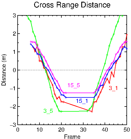
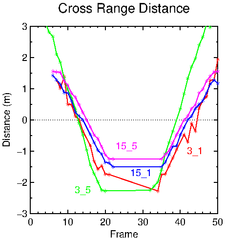
    Thank you for correcting me on item one.  I did a small parametric study for aoa performance as a function of the number of receiving and transmitting antenna.  The scene involved a reflector traversing in front of the sensor and then back.  The results are attached.  I variation were

    channelCfg 3 1 0

    channelCfg 7 1 0

    channelCfg 15 1 0

    channelCfg 3 5 0

    channelCfg 7 5 0

    channelCfg 15 5 0

    Two questions.

    1. I obtained no results when three receiving antennas were configured (cases channelCfg 7 1 0 and channelCfg 7 5 0).  What is the reason for this?

    2.  The result quality was proportional to the number of processed chirps.  But how come the channelCfg 3 5 0 results are off by a factor of two for distance traversed.

    I was using the standard oob demo visualizer and sensor loads.

    Al

  • Nitin,

    I would kindly appreciate your thoughts on for the questions in the prior posting. It is perplexing to me.
    1. Why no response was observed when three receiving antennas where used but responses for when 2 or 4 were used.
    2. Why one response was off a factor of two.
    Thanks.

    Al
  • Allen,

    1. I obtained no results when three receiving antennas were configured (cases channelCfg 7 1 0 and channelCfg 7 5 0). What is the reason for this?
    2. Why one response was off a factor of two.

    a) I am not sure I understand what you mean by no results?
    b) What does the plot represent? I assume it's the distance of the object for different frames.
    c) Are you changing the channel configuration at run-time? This is wrt your initial question about getting no results for 3RX.
    d) Please provide details of your test setup: The chirp configuration used (Max range, Max velocity, Velocity resolution) and how is the target moving in front of the sensor e..g direction of movement, max speed etc?


    Regards
    -Nitin
  • Hi Nitin,

    I collected some data with the mmwave demo visualizer using the demo software for a reflector moving ~2 m/s, 3 meter in front of the sensor at boresight.  The reflector was moving first left to right then it stopped and then moved right to left.  I used the default sensor parameters from the visualizer except I varied the number of antennas used for a number of different cases.  I collected data for 5 seconds so I got about 50 frames for each cases. 

    What I plotted was the x value for the largest detected object for each frame.  The cfarCfg had these as the parameters: 0 2 8 4 3 0 4000.

    1. What I meant is the for the cases

    channelCfg 7 1 0

    channelCfg 7 5 0

    I had no detected objects.  This really surprised me since the other cases that I plotted the data from and included, all had data.  I see no reason that when the sensor was configured for three receive antennas, that should not be present.

    2. The plotted data is the observed x location of the reflector as the reflector was moving from left to right, stopping and the moving from right to left.  The track is about 3m in length.

    3. I changed the configuration each time each case by reading an unique configuration file.  The only difference for each config file is the channelCfg parameters.

    4. The typical config file is

    sensorStop
    flushCfg
    dfeDataOutputMode 1
    channelCfg 7 1 0
    adcCfg 2 1
    adcbufCfg 0 1 0 1
    profileCfg 0 77 429 7 57.14 0 0 70 1 240 4884 0 0 30
    chirpCfg 0 0 0 0 0 0 0 1
    frameCfg 0 0 16 0 100 1 0
    lowPower 0 0
    guiMonitor 1 1 0 0 0 1
    cfarCfg 0 2 8 4 3 0 4000
    peakGrouping 1 1 1 1 229
    multiObjBeamForming 1 0.5
    clutterRemoval 1
    calibDcRangeSig 0 -5 8 256
    compRangeBiasAndRxChanPhase 0.0 1 0 1 0 1 0 1 0 1 0 1 0 1 0 1 0 1 0 1 0 1 0 1 0
    measureRangeBiasAndRxChanPhase 0 1.5 0.2
    CQRxSatMonitor 0 3 5 123 0
    CQSigImgMonitor 0 119 4
    analogMonitor 1 1
    sensorStart

    I hopes this better explains the environment and the test.  I wanted to see the effects on the x position calculation bases upon the number of antennas (both receiving and transmitting).  I assume the more, the better if averaging is being performed.  It appear that more virtual antennas are better since a smoother x variations were observed which I assume is to do to averaging.

    My other result that I could not explain is that one of the four curves I plotted had a numerical value twice the x variation that of the other three had which again is hard from me to explain.  Same conifg file contents except that I varied the channelCfg line and I used the same processing software to read in and plot the data.  The  maximu x variation should be +/- 1.5 m since the track is about 3 m in length.

    Thanks.

    Al

  • Allen,

    1. Between the two files where you varies the channel config as listed above i.e.

    channelCfg 7 1 0
    Vs
    channelCfg 7 5 0

    You are varying the number of transmitters. However, there will be no difference between these two configs if you do not use the enabled transmitter in a chirp config command. In other words, Channel config only enables/ disables channels at global level but you still need to use the transmitter in a chirpCfg command to actually chirp with it. The number of receivers is the same in both cases.

    Going by your setup description and the plot, the reason you may not detect the object is when it comes to a stop (when changing direction) and you have static clutter removal enabled in your configuration.

    2. You'll need to provide your complete configuration file for the two scenarios (not just channel config) where you see the observed difference.

    -Nitin
  • Hi Nitin,

    Thank you for looking at this in greater detail.

    1. I have included the two configuration files for  your review.  I believe the chirpCfg's have been appropriately set up.  I was successful for the other configurations (15_5, 15_1 and 3-5,3_1).

    2. Yes I understand with clutter removal that there should not be any detected objects when the reflector is stationary.  This was shown for the cases (15_5, 15_1 and 3-5,3_1)  in the plot I provided.  However, I did not obtain any detected objects for the cases, 7_5 and 7_1, when the reflector was moving either as I did for the four other cases.  I ran 6 cases, processed the data all the same and obtained data for only 4 cases.  I find this to be strange.

    3. I observed one other strange result for the 3_5 case.  The resulting x distance was off by a factor of 2 as the plot showed.

    You may not be able to explain the observations in 2 and 3 but if you can, it would be good to know.

    Al

     7_

    7_5

    sensorStop
    flushCfg
    dfeDataOutputMode 1
    channelCfg 7 5 0
    adcCfg 2 1
    adcbufCfg 0 1 0 1
    profileCfg 0 77 429 7 57.14 0 0 70 1 240 4884 0 0 30
    chirpCfg 0 0 0 0 0 0 0 1
    chirpCfg 1 1 0 0 0 0 0 4
    frameCfg 0 1 16 0 100 1 0
    lowPower 0 0
    guiMonitor 1 1 0 0 0 1
    cfarCfg 0 2 8 4 3 0 4000
    peakGrouping 1 1 1 1 229
    multiObjBeamForming 1 0.5
    clutterRemoval 1
    calibDcRangeSig 0 -5 8 256
    compRangeBiasAndRxChanPhase 0.0 1 0 1 0 1 0 1 0 1 0 1 0 1 0 1 0 1 0 1 0 1 0 1 0
    measureRangeBiasAndRxChanPhase 0 1.5 0.2
    CQRxSatMonitor 0 3 5 123 0
    CQSigImgMonitor 0 119 4
    analogMonitor 1 1
    sensorStart

    7_1

    sensorStop
    flushCfg
    dfeDataOutputMode 1
    channelCfg 7 1 0
    adcCfg 2 1
    adcbufCfg 0 1 0 1
    profileCfg 0 77 429 7 57.14 0 0 70 1 240 4884 0 0 30
    chirpCfg 0 0 0 0 0 0 0 1
    frameCfg 0 0 16 0 100 1 0
    lowPower 0 0
    guiMonitor 1 1 0 0 0 1
    cfarCfg 0 2 8 4 3 0 4000
    peakGrouping 1 1 1 1 229
    multiObjBeamForming 1 0.5
    clutterRemoval 1
    calibDcRangeSig 0 -5 8 256
    compRangeBiasAndRxChanPhase 0.0 1 0 1 0 1 0 1 0 1 0 1 0 1 0 1 0 1 0 1 0 1 0 1 0
    measureRangeBiasAndRxChanPhase 0 1.5 0.2
    CQRxSatMonitor 0 3 5 123 0
    CQSigImgMonitor 0 119 4
    analogMonitor 1 1
    sensorStart

  • Hi Allen,

    It turns out that the 3RX case is not supported in the SDK out of box demo. The SDK demo supports using either 1, 2 or 4 RX channels only which is why the above configurations do not generate any detected objects.

    Regards
    -Nitin
  • Hi Nitin,

    Thanks for the additional feedback.  I know that the gui provides the 1, 2 and 4 Rx options from the configuration page.  I was supplying configuration files from the plot page where the user could load in their own configurations.  I would have thought that the gui would process the user supplied configurations but maybe not.

    I still do not know why the scaling for the  3_5 case (2 rx and 2 tr, green curve) was off by a factor of 2.

    I am marking this as resolved

    Thanks for your time.

    Al