This thread has been locked.

If you have a related question, please click the "Ask a related question" button in the top right corner. The newly created question will be automatically linked to this question.

LM73: Incorrect temperature readings from LM73

Part Number: LM73

Hi,

As the title suggests, I am seeing abnormal temperature readings with the LM73:

- The abnormal readings are not directly after power-on, but after a certain amount of time of valid readings. I have 10 different units and they all exhibit the failure within about 2 hours of run time, but the exact time varies.

- The abnormal readings of the Temperature Data Register are usually around the same value: 0xF5XX or 0xF6XX, which corresponds with a negative temperature (around -20 degrees C). The temperature readings before the incorrect ones were around 35 degrees C. Once an incorrect value is read from the LM73, the temperature readings return to the valid range (~35degC) again.

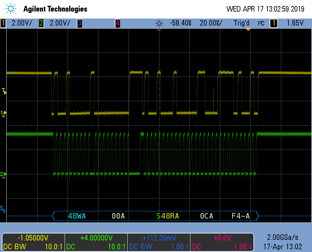
- The problem is not I2C noise, because the microcontroller is interfacing with other I2C peripherals on the same I2C lines with no corrupted data at all. Any I2C noise would be expected to affect all devices on the same bus. The microcontroller is not seeing any problems with the I2C protocol itself (misplaced start/stop conditions, bus arbitration or NACKs).

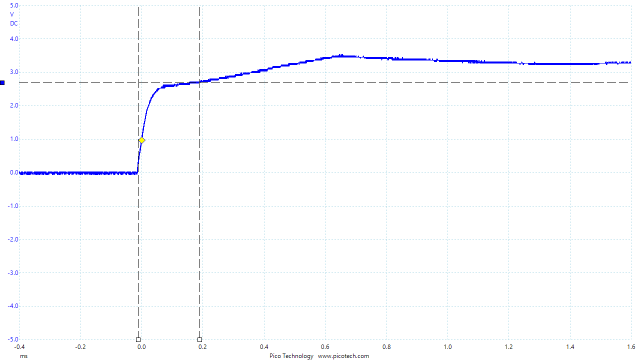
- The VDD ramp rate is faster than the minimum of 0.7V/ms specified in Section 9 of the LM73 datasheet. The VDD takes about 400us to rise from 0V to 3V3, corresponding to a ramp rate of about 8V/ms. The microcontroller software is also performing the software reset sequence in Section 9 of the datasheet, to prevent any problems with corrupted data due to POR ramp-rate.

This problem appears to be very similar to that experienced by others on this forum, however I've not been able to find a definitive answer in those posts as to why the LM73 behaves in this way.

Kind regards,

Tom

  • Hello Tom,

    Thanks for the detailed post on the issue. A few questions though

    1. Can you please share the supply ramp rate and data transaction snapshot?
    2. What is the rate at which the application reads the LM73?
  • Hi Amit,

    Thanks for your quick response. Please see attached for a capture of the VDD ramp rate (I've attached both .png and .psdata format). As you can see, it takes ~0.2ms for the supply to reach 2.7V.

    It is a quite difficult for me to capture a single LM73 data transaction, because there are other I2C transactions on the same bus. I will try to get that for you using our more advanced oscilloscope.

    The rate at which the application is reading the LM73 temperature register is once every 100ms. The LM73 is configured for 14-bit resolution in continuous conversion mode.

    Thanks,
    Tom
  • Oops, forgot to attach the file. Here it is...

  • Hello Tom,

    Thanks for the waveform. I would suggest modifying the ramp rate to match the specification using additional bulk capacitors. As for the other issue, since you are reading an incorrect value, did you try changing the sampling interval from once every 100 ms, to a little over twice the conversion time in 14-bit mode, i.e. 2 x 112 ms + 1 ms = 225 ms.

    I am suspecting it has to do something with the read of the temp sensor and the conversion cycle occurring at the same time. Is that something your application can perhaps use?
  • Hi Amit,

    I have now obtained a trace of the I2C transaction. See below - this corresponds to a valid temperature reading of 0x0CF4 (25.9 degC). I have now set up my scope to trigger when a negative temperature reading occurs (data byte 1 = 0x0F) to verify that it's not I2C noise, and I'm waiting for the issue to occur.

    Regarding your comment "I would suggest modifying the ramp rate to match the specification using additional bulk capacitors" - we have a 100nF bypass capacitor on the VDD signal, which is what Figure 14 in the datasheet specifies. The minimum ramp rate is specified in Section 9 of the datasheet as 0.7V/ms. Is there also a maximum ramp rate?

    Here is a snippet from our schematic (there are 4K7 pull-ups on the I2C lines, not shown here):

    Also what do you mean by "I am suspecting it has to do something with the read of the temp sensor and the conversion cycle occurring at the same time.". In Section 6.5 of the datasheet it says:

    "(3) This specification is provided only to indicate how often temperature data is updated. The LM73 can be read at any time without regard to conversion state (and will yield last conversion result)"

    Surely I can read the Temperature Data Register at any time??

    Thanks,

    Tom

  • Hello Tom,

    Yes, please ignore the earlier message on the ramp rate, as you are performing a soft reset as well.

    The issue as it seems to me is that the foot note (3) allows that the data be read at any time. But for some reason, there seems to be a conflict when the data read starts and a conversion is also ongoing. That is why the issue does not appear that often and it seems to correct itself on the next read. That is why I am suggesting using the slower read work around to first make sure that it is not the same scenario.
  • Hi Amit,

    I have tried slowing down the polling to once every 225ms as suggested, but the error still occurs. Just for investigation, I also tried a shorter polling periods of 50ms and 25ms, and the error is there. I have managed to capture an I2C trace when the incorrect reading is read:

    As you can see, the reading is 0xF5C4, which corresponds to -20.375 degrees C. It's clearly not I2C noise causing this.

    At this point I'm not sure what I can do. Seems like the LM73 is intent on giving me incorrect readings occasionally, and I will have to do something clever in software to get around the issue, like disregarding a reading if it is outside a certain 'valid' range and just use the previous reading to "ride through" these incorrect ones.

    Thanks,

    Tom

  • Hello Tom,

    I have been able to replicate the issue on my side as well, but with 225 ms, i.e. 2 times the conversion period in 14-bit mode, the issue does not occur at all. I would suggest returning the part to TI, so that we can check what is happening.
  • Hello Tom,

    Is there any further update on this thread?
  • Hi Amit,

    I've tried it once more with the 225ms polling rate on the 10 devices we have here, and the problem still occurs. I can't explain why you're not seeing it too. Are you sure the issue doesn't occur at all, or it just takes longer to occur? For me the issue can take up to a few hours to occur normally (i.e. with 100ms polling period), so I would expect that with 225ms period the issue would still occur but might just take longer, because there is a lower chance of reading the Data Register at the wrong moment. I had to leave the 10 devices running overnight to see the failure on them with a 225ms polling period.

    Sadly returning the part to TI is not something we can easily do as they are surface mounted to our devices. Unless we can find a cause for this, I think I am just going to have to 'ride through' the issue in software. I can detect when the temperature reading is outside of an expected range and ignore the reading (use the last known good reading instead), until the LM73 starts giving me good readings again.

    Thanks,

    Tom

  • Hello Tom.

    I have left the WA running on a weekend and it has not failed 2 days of the read cycles.
  • Hi Amit,

    Ok. That's very strange, I can't explain why I'm seeing the issue and you aren't. I'm still unclear as to why the poll rate should affect the temperature reading. The datasheet clearly says I can read the Data Register at any time. Is the Data Register not double-buffered in the LM73?

    I am now trying a software build with a 1000ms poll rate to see if that makes any difference. I suspect it will be tomorrow before I can verify whether that has failed or passed.

    Meanwhile, our hardware engineer has suggested that we should try to induce the problem by introducing some ripple on the VDD, to see if that makes the problem occur. Do you have any data on what is the lowest that VDD can go without causing bad readings, or how much VDD ripple is acceptable?

    Thanks,
    Tom
  • Hello Tom

    As I mentioned earlier, the read transaction seems to be causing the issue when a temperature conversion happens at the same time. Even though the datasheet mentions that the temperature can be read at any time, I believe that reading it at over 2x the conversion time will prevent the issue from occurring. Let me know what results you get from your tests. Ideally I would like to have the parts which does not seem to follow the 2x solution, to figure out what is happening, since I cannot reproduce it at 2x read time.
  • Hi Amit,

    But surely, polling the data register at any periodic rate is eventually going to align with when the sensor is performing the temperature conversion, because the host software's clock and the LM73 clock are not synchronized. So I don't understand why the 2x polling rate would prevent this from happening?

    I will see if we can return a sensor that is exhibiting the fault to you, so you can do some more diagnostics.

    Thanks,

    Tom

  • Hello Tom,

    The working hypothesis is that if a read corrupts the data, the next conversion will correct the same. By reading at 2x the conversion time, if the current read corrupts the data, then the next read shall occur after the conversion by which time a correct conversion would have corrected the reading.
  • Hi Amit,

    Right, in that case I think I misunderstood the whole idea. You're saying that the 225ms poll rate doesn't prevent me from getting a corrupted reading in the first place, it just means that after a single bad reading I can guarantee that the next reading is a good one, correct?

    So could you confirm, when you said you ran it on your end with a 225ms poll rate over the weekend and saw no errors - did you see *any* corrupted readings, or did you mean that you did see single occurrences of bad readings, but they were corrected upon the next read?

    On my end, I am definitely still seeing single occurrences of corrupted readings with a 225ms poll rate.

    Thanks,

    Tom

  • Hello Tom,

    TomW said:
    Right, in that case I think I misunderstood the whole idea. You're saying that the 225ms poll rate doesn't prevent me from getting a corrupted reading in the first place, it just means that after a single bad reading I can guarantee that the next reading is a good one, correct?

    No. What I am saying is when a read corrupts the conversion data, the corrupted value gets loaded into the temperature register for the next read cycle. Howvever when the next conversion happens the corrupted value gets "corrected", subsequently to which the read is always correct.

    Yes, I can confirm that the reads were no longer corrupted with ~225 ms of read interval.

    On your side, is there any timing variation you see on the 225 ms? I.e. it is sometimes 224 and sometimes 226 ms?

  • Hi Amit,

    Right, I see what you are saying now. That makes sense.

    Yes, it's possible that the timing of the software is not that accurate. I will try increasing the software timeout to something like 230ms and see if that makes a difference...

    Thanks,
    Tom
  • Hello Tom,

    Were you able to test the device with the 230 ms software timeout between reads?
  • Hi Amit,

    Yes, I did manage to test with a longer interval between polling. Due to the design of my scheduler, the easiest for me is to pick multiples of 6.25ms, so I tried both 231.25ms and 237.5ms. I saw occasional invalid readings with both of them, so no difference from the 100ms default rate.

    However, since then I have managed to implement a software workaround where I store the previously known good reading, and if the new reading differs by more than 0.5 degrees C from the previous reading, I reject the new reading and use the old one instead. I do this a maximum of 3 times and then I flag a downstream fault. This appears to work perfectly in "riding through" these occasional bad readings from the sensor. Since we know that under normal operating conditions, the PCB temperature can never change by more than 0.5 degC within 100ms, we are satisfied that this solution will work for our needs.

    I think we can go ahead and close this thread. Many thanks for your time and effort in trying to debug this.

    Kind regards,

    Tom