This thread has been locked.

If you have a related question, please click the "Ask a related question" button in the top right corner. The newly created question will be automatically linked to this question.

PGA460-Q1: Short Distance Measurement with High Frequency Transducer

Part Number: PGA460-Q1
Other Parts Discussed in Thread: BOOSTXL-PGA460, PGA460

Hi,

I am using BOOSTXL-PGA460 EVM for my project. I tested the EVM with the shipped transducer Murata MA58MF14-7N and it was working perfectly for distance measurement above 25cm. As my application demands object sensing in the range of 10cm- 30cm I switched to high frequency transducer of 300KHz. I even replaced the transformer on the EVM as per suggested transducer and transformer combinations on ti forum. Currently I am using Multicomp MCUSD13A300B09RS transducer and TDK/EPCOS B78416A2386A003 transformer but i am not able to get significant echo data dump. I am using the EVM in transformer driven bi-static mode. 

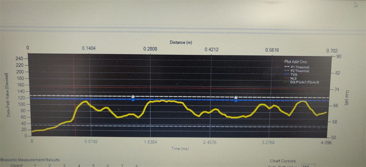
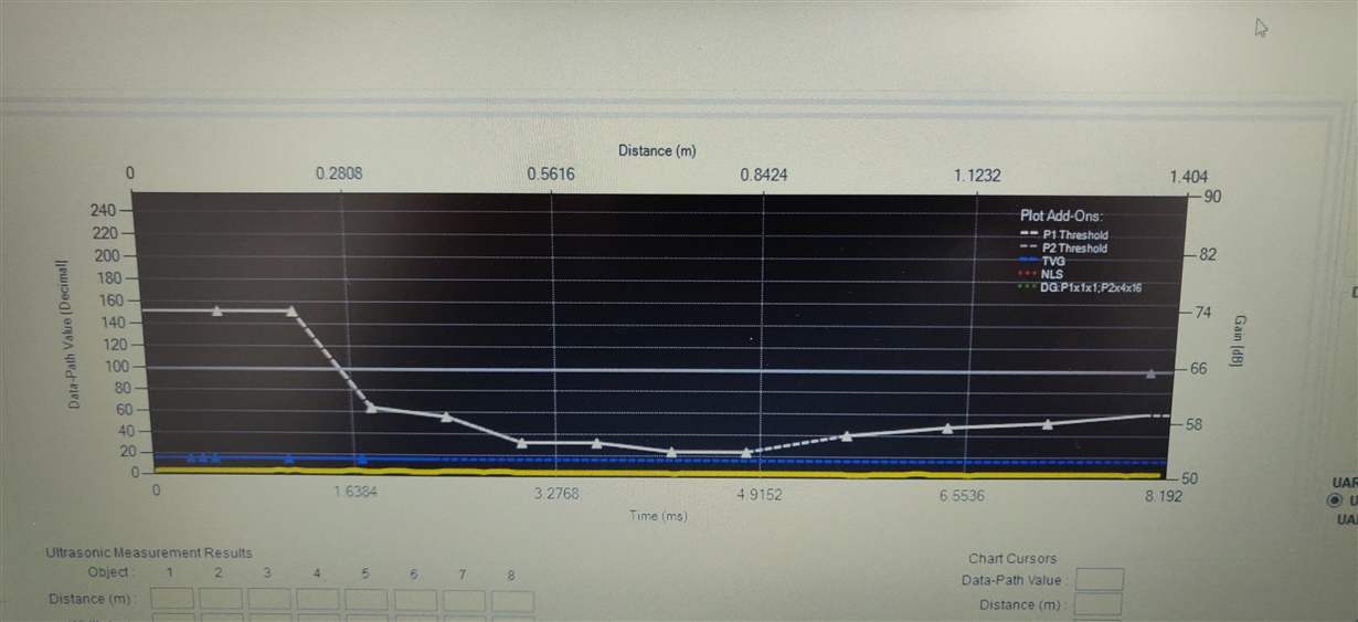
The GUI Echo data dump capture image is shown below:

As you can see from the image that there is not even initial burst saturation on EDD.

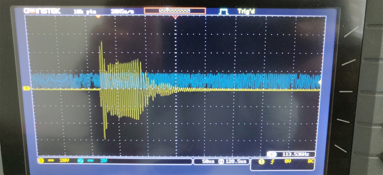
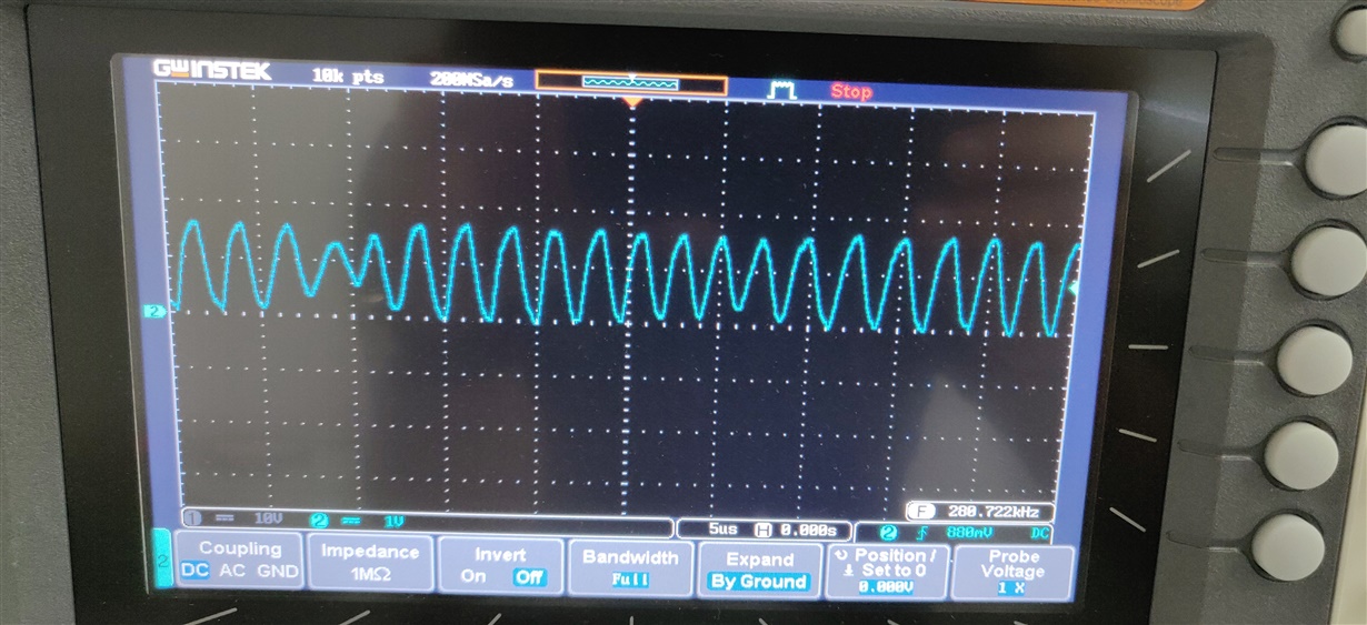
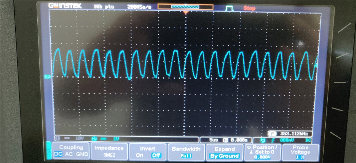
The DSO captures of PGA signal is attached below:

In the above picture yellow channel is transducer input and blue channel is signal on test pin which is muxed as Analog Front End output.

Please find attached herewith my configuration file also.

GRID_USER_MEMSPACE-2019-06-11_150313.txt
;GRID_USER_MEMSPACE
00 (USER_DATA1),00
01 (USER_DATA2),00
02 (USER_DATA3),00
03 (USER_DATA4),00
04 (USER_DATA5),00
05 (USER_DATA6),00
06 (USER_DATA7),00
07 (USER_DATA8),00
08 (USER_DATA9),00
09 (USER_DATA10),00
0A (USER_DATA11),00
0B (USER_DATA12),00
0C (USER_DATA13),00
0D (USER_DATA14),00
0E (USER_DATA15),00
0F (USER_DATA16),00
10 (USER_DATA17),00
11 (USER_DATA18),00
12 (USER_DATA19),00
13 (USER_DATA20),00
14 (TVGAIN0),44
15 (TVGAIN1),44
16 (TVGAIN2),44
17 (TVGAIN3),08
18 (TVGAIN4),64
19 (TVGAIN5),9A
1A (TVGAIN6),99
1B (INIT_GAIN),40
1C (FREQUENCY),64
1D (DEADTIME),10
1E (PULSE_P1),0A
1F (PULSE_P2),14
20 (CURR_LIM_P1),3F
21 (CURR_LIM_P2),7F
22 (REC_LENGTH),07
23 (FREQ_DIAG),10
24 (SAT_FDIAG_TH),EE
25 (FVOLT_DEC),7C
26 (DECPL_TEMP),0F
27 (DSP_SCALE),00
28 (TEMP_TRIM),00
29 (P1_GAIN_CTRL),00
2A (P2_GAIN_CTRL),22
2B (EE_CRC),1F
40 (EE_CNTRL),00
41 (BPF_A2_MSB),57
42 (BPF_A2_LSB),F9
43 (BPF_A3_MSB),F9
44 (BPF_A3_LSB),A5
45 (BPF_B1_MSB),03
46 (BPF_B1_LSB),2D
47 (LPF_A2_MSB),7E
48 (LPF_A2_LSB),67
49 (LPF_B1_MSB),00
4A (LPF_B1_LSB),CD
4B (TEST_MUX),20
4C (DEV_STAT0),80
4D (DEV_STAT1),00
5F (P1_THR_0),44
60 (P1_THR_1),44
61 (P1_THR_2),44
62 (P1_THR_3),44
63 (P1_THR_4),55
64 (P1_THR_5),55
65 (P1_THR_6),9C
66 (P1_THR_7),D0
67 (P1_THR_8),72
68 (P1_THR_9),10
69 (P1_THR_10),63
6A (P1_THR_11),28
6B (P1_THR_12),30
6C (P1_THR_13),34
6D (P1_THR_14),3C
6E (P1_THR_15),00
6F (P2_THR_0),FE
70 (P2_THR_1),40
71 (P2_THR_2),4A
72 (P2_THR_3),FD
73 (P2_THR_4),38
74 (P2_THR_5),E2
75 (P2_THR_6),63
76 (P2_THR_7),7F
77 (P2_THR_8),56
78 (P2_THR_9),69
79 (P2_THR_10),40
7A (P2_THR_11),A3
7B (P2_THR_12),CF
7C (P2_THR_13),90
7D (P2_THR_14),59
7E (P2_THR_15),C3
7F (THR_CRC),CC
EOF
 

Kindly help me in resolving this issue.

Thanks 

Nishant Sharma

  • Hi Nishant,

    May I ask why you are using the high-frequency transducer in a bi-static mode? If your targeted range is 10~30cm, then a high-frequency transducer in mono-static mode should be able to achieve this range. You should use a low-frequency transducer in bi-static mode to achieve 10~30cm ranging. Note: bi-static mode implies two transducers - one transmitting and the other receiving.

    Let us assume you need bi-static mode for this response:

    1) The directivity of the MCUSD13A300B09RS is 10 degrees, which is very narrow. If you have a bi-static (two transducer) configuration, you will need these transducers to be very close to each other, and potentially at an angle. When transducers have this narrow of a field of view, I would not recommend a bi-static approach. If you'd like to check if your bi-static pair is working, have the transmitting and receiving elements face each other.

    2) Ensure you have removed the tuning capacitor and damping resistor in parallel to the transducer. The default value of these matching components were optimized for the Murata MA58MF14-7N transducer that comes with the EVM.

    3) I checked your register settings with a different 300kHz transducer I have. Your settings do work with my 300kHz transducer, so I suspect your issue is due to the fact that you are using a bi-static configuration instead of a mono-static configuration.

  • Hi Akeem,

    I am using bi-static mode because in my end application i have to transmit from one transmitter and receive at other transducer. I haven't removed tuning capacitor and damping resistor. Are they to be replaced by components of some other value? If so, what are the ratings of capacitor and resistor to be used? I have tried placing transducers very close and upfront to each other but still there was no change in echo data dump. Thanks and waiting for your further response. 

    Nishant Sharma

  • Hi Akeem,

    I was waiting for your response for resolving this issue.

    Nishant Sharma

  • Hi Nishant,

    You will need to remove the original tuning capacitor and damping resistor. You do not need to substitute these values for initial testing. Most high-frequency transducers do not require any matching components. In addition, for a bi-static pair, matching is less important since the receiver is not saturated during the transmit burst/decay.

    How far apart are your two sensors? Can you bring them very close to one another (i.e. 10cm apart) to test the performance. You may also need to increase your time varying gain and/or digital gain multiplier values.

    It may be that a larger drive voltage is required to generate sufficient sound pressure level since this transducer has a drive voltage rating of 400V. Can you provide the schematic of your solution for me to verify your connections?

  • Hi Akeem,

    Thanks for your response. I will test the setup after removing the tuning capacitor and damping resistor. My final application requirement is to keep the transducers 10-25cm apart. I have replaced the transformer on the EVM kit, so the schematic is same as that of BOOSTXL-PGA460 EVM. As seen from DSO captures voltage applied to transducer is around 100V peak to peak. If a higher voltage is required to generate sufficient Sound Pressure level, then how to increase the voltage input to the transducer? Currently I am using USB supply to power the EVM.

    Thanks 

    Nishant Sharma

  • Hi Akeem,

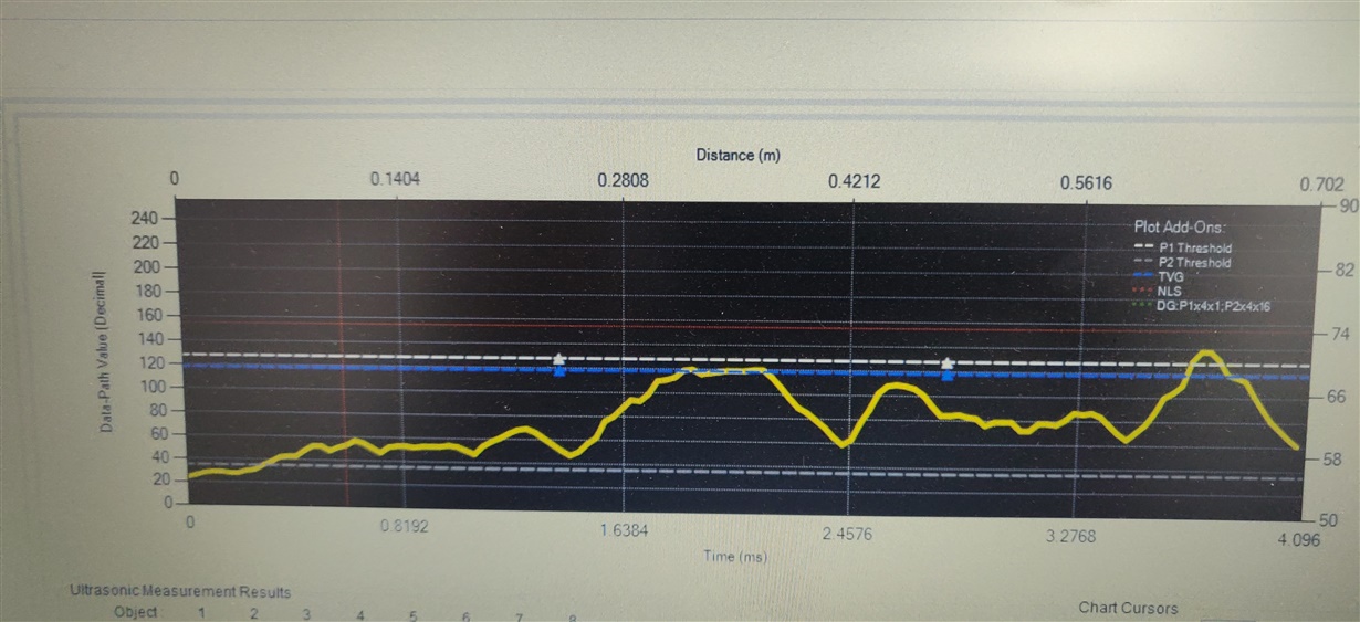
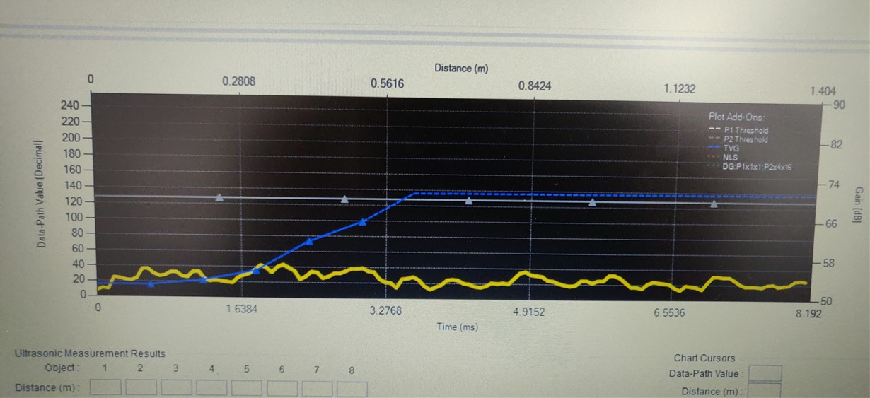
    I removed the tuning capacitor C15 and damping Resistor R15 from the EVM board but still my EDD plot is  random. Now I am testing PGA460 in mono static mode as advised by you. My measurement distance is around 10 cm.  With first burst and listen command, the  EDD on GUI is  as shown below:

    Then for the next burst and listen command EDD is shown below:

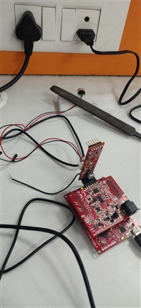
    I have kept all the TVGs and Threshold levels at mid code values. But you can see from the above EDD that there is no similarity in the data received. I am not even able to observe initial saturation in EDD. My test setup is shown in the image below:

    Please find attached PGA460 memory map file for register settings

    GRID_USER_MEMSPACE-2019-06-18_163017.txt
    ;GRID_USER_MEMSPACE
    00 (USER_DATA1),00
    01 (USER_DATA2),00
    02 (USER_DATA3),00
    03 (USER_DATA4),00
    04 (USER_DATA5),00
    05 (USER_DATA6),00
    06 (USER_DATA7),00
    07 (USER_DATA8),00
    08 (USER_DATA9),00
    09 (USER_DATA10),00
    0A (USER_DATA11),00
    0B (USER_DATA12),00
    0C (USER_DATA13),00
    0D (USER_DATA14),00
    0E (USER_DATA15),00
    0F (USER_DATA16),00
    10 (USER_DATA17),00
    11 (USER_DATA18),00
    12 (USER_DATA19),00
    13 (USER_DATA20),00
    14 (TVGAIN0),88
    15 (TVGAIN1),88
    16 (TVGAIN2),88
    17 (TVGAIN3),82
    18 (TVGAIN4),08
    19 (TVGAIN5),20
    1A (TVGAIN6),81
    1B (INIT_GAIN),20
    1C (FREQUENCY),64
    1D (DEADTIME),80
    1E (PULSE_P1),14
    1F (PULSE_P2),14
    20 (CURR_LIM_P1),3F
    21 (CURR_LIM_P2),3F
    22 (REC_LENGTH),07
    23 (FREQ_DIAG),11
    24 (SAT_FDIAG_TH),22
    25 (FVOLT_DEC),69
    26 (DECPL_TEMP),4F
    27 (DSP_SCALE),00
    28 (TEMP_TRIM),00
    29 (P1_GAIN_CTRL),02
    2A (P2_GAIN_CTRL),22
    2B (EE_CRC),C3
    40 (EE_CNTRL),00
    41 (BPF_A2_MSB),5B
    42 (BPF_A2_LSB),05
    43 (BPF_A3_MSB),FC
    44 (BPF_A3_LSB),CE
    45 (BPF_B1_MSB),01
    46 (BPF_B1_LSB),99
    47 (LPF_A2_MSB),7F
    48 (LPF_A2_LSB),33
    49 (LPF_B1_MSB),00
    4A (LPF_B1_LSB),67
    4B (TEST_MUX),00
    4C (DEV_STAT0),80
    4D (DEV_STAT1),00
    5F (P1_THR_0),88
    60 (P1_THR_1),88
    61 (P1_THR_2),88
    62 (P1_THR_3),88
    63 (P1_THR_4),88
    64 (P1_THR_5),88
    65 (P1_THR_6),84
    66 (P1_THR_7),21
    67 (P1_THR_8),08
    68 (P1_THR_9),42
    69 (P1_THR_10),10
    6A (P1_THR_11),80
    6B (P1_THR_12),80
    6C (P1_THR_13),80
    6D (P1_THR_14),80
    6E (P1_THR_15),00
    6F (P2_THR_0),FA
    70 (P2_THR_1),40
    71 (P2_THR_2),4A
    72 (P2_THR_3),FD
    73 (P2_THR_4),38
    74 (P2_THR_5),E2
    75 (P2_THR_6),23
    76 (P2_THR_7),77
    77 (P2_THR_8),56
    78 (P2_THR_9),69
    79 (P2_THR_10),40
    7A (P2_THR_11),A3
    7B (P2_THR_12),CF
    7C (P2_THR_13),90
    7D (P2_THR_14),59
    7E (P2_THR_15),C3
    7F (THR_CRC),D7
    EOF
    

    In your earlier answer you suggested that it might be required to input higher voltage for Multicomp MCUSD13A300B09RS transducer for generating sufficient SPL, so kindly suggest me how to proceed for doing so. You also stated that you have tested my register setting on your 300KHz transducer and it worked for you. Can you share the part number of the transducer which you are using and what was the distance range for which you tested. Waiting for your early response.

    Thanks

    Nishant Sharma
  • Hi Akeem,

    I was hoping you could provide input for resolving my issues. In anticipation of your early response.

    Thanks 

    Nishant Sharma
  • Hi Nishant,

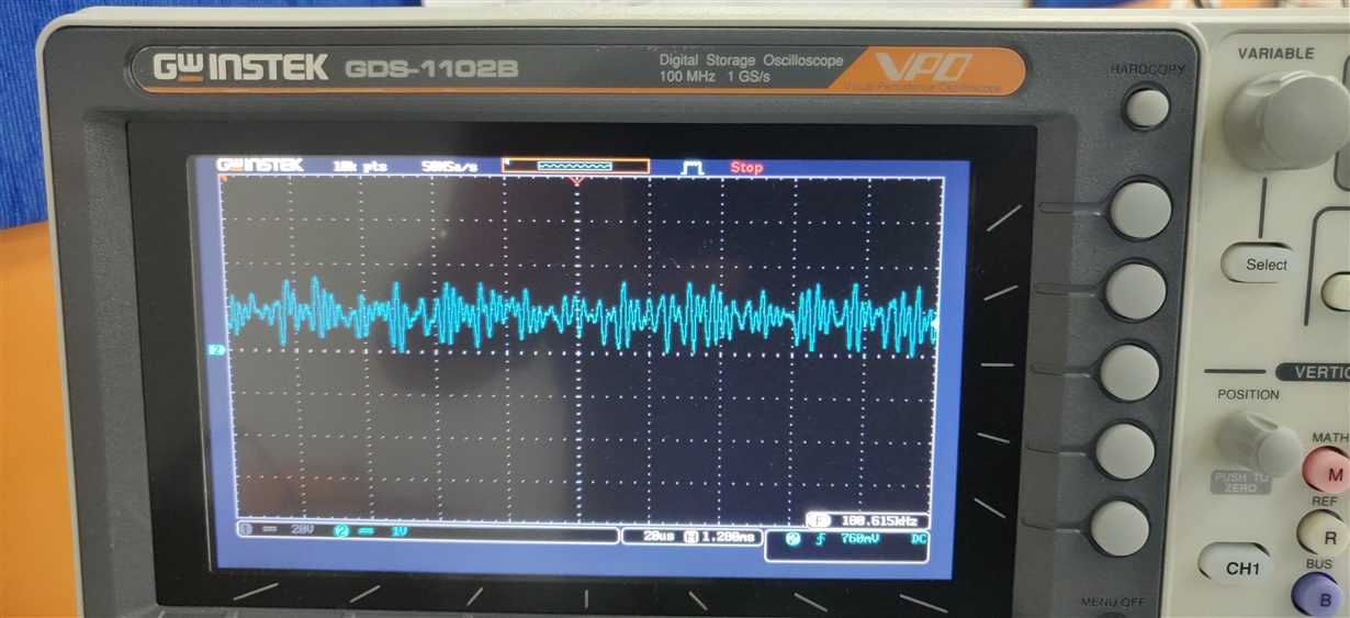
    There appears to be a large noise signature present on the echo data dump output. I suspect that by finding the root cause of the noise, the performance should improve. To help debug the noise, try the following:

    1. Use an external power supply to power the EVM. In some cases, the USB boost circuit can introduce ripple to VPWR if the source is not stable. Any ripple on VPWR will then translate onto the AVDD regulator, which the front end references. If AVDD is unstable, then the noise will be amplified. You can probe AVDD to see if it shows any ripple. You can also try adding a low-pass filter RC circuit at the VPWR pin.
    2. For the bi-static configuration, did you also remove zero ohm resistor R36 to decouple the receive element from the transmit element?
    3. When you remove all transducers, and perform a listen only measurement while the transducer socket is open, does the noise floor level remain the same? Be sure your bi-static circuit matches the description of PGA460 FAQ #4.4.5 (http://www.ti.com/lit/an/slaa733/slaa733.pdf).

    The 300kHz transducers I have verified are from Murata and Steminc, though other customers have successfully used various Multicomp transducers. I typically can detect downwards of 3~5cm with 300kHz transducers, and upwards of 0.5~+1m.

    To drive the Multicomp with a stronger transmit voltage, using an external power supply will help since you can set both VPWR and the transformer center-tap up to 15V in transformer mode.

  • Hi Akeem,

    Thanks for your time and detailed explanation. I removed R36 for bi-static configuration. I performed the listen only command with USB power and I can observe from EDD that there is no noise due to USB boost circuit. EDD plot is shown below:

    So it is clear that boost circuitry is not the cause for noise. 

    Now when I connect the transducer and perform listen only command I can observe noise in the Echo data dump on GUI.

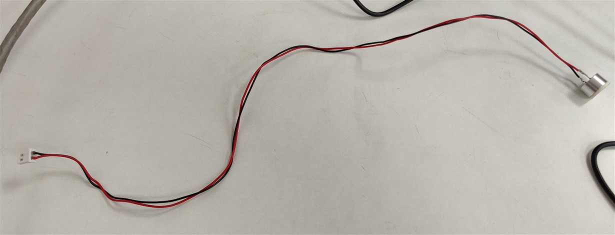
    I tested the EVM by using external power supply and performing Listen only command but still the noise persists. My test setup wire length from daughterboard to transducer is around 35cm and it is not shielded wire. Please find attached image of transducer with connection.

     Is it possible that it might be catching noise from surroundings? What can be the maximum length of connection between transducer and connector on dauhterboard? 

    Thanks

    Nishant Sharma
  • Hi Nishant,

    The termination between the receiving transducer and the return path input should be made as short as possible, so the length of your transducer cable could be problematic. You have a few options for debug:

    • Reduce the length of the cable.
    • Use a twisted pair cable.
    • Shield the cable to ground.

    I know you need a two sensor bi-static configuration, but have you tried using this MCUSD13A300B09RS transducer in a mono-static mode to check its single sensor transmit/receive performance? This will also serve as a performance sanity check.

  • Hi Akeem,

    Thank you for timelyt reply. I have reduced the length of cable and tested the setup but still there is only noise on the EDD. I have been testing the MCUSD13A300B09RS transducer in mono-static mode only. Earlier i was using bi-static configuration but then i switched to mono-static. Main issue i am facing is that there is not even initial burst saturation at EDD which can be seen when we are using Murata MA58MF14-7N transducer. This is forcing me to doubt about the transmission of ultrasonic wave and whether my transducer is working or not. The rated voltage of MCUSD13A300B09RS is around 400V and from what i have read and as observed on DSO captures EVM can supply around 120 V. So will this 120 V be enough to generate required sound pressure level? Another question is how i can test whether my transducer is even generating a ultrasonic wave? 

    I am also thinking of switching to other transducer such as Murata MA300D1-1 as it requires lower input voltage. But it is out of stock at all the online component suppliers. All the high frequency transducers listed on your reference for "Air coupled ultrasonic transducers and transformers"  are out of stock and have 6 months lead time. It would be of great help if you could provide part number of high frequency transducer which is already verified by you for short range measurements. 

    Thanks 

    Nishant Sharma
  • Part Number: BOOSTXL-PGA460

    Hi,

    I am using BOOSTXL-PGA460 for the development of an application. The application specification requires object detection in the range of 10cm-30cm. According to the literature for short range detection high frequency transducer must be used. So we are in process of acquiring 300 KHz Murata MA300D1-1 transducer and want to use it with the EVM. Can you provide the hardware changes required for short range measurement using closed top transducer MA300D1-1.

    Thanks 

    Nishant Sharma
  • Hi Nishant,

    Before you restart your high frequency effort using the MA300D1-1, please note that since you are using a bi-static configuration, you can also use a low frequency transducer pair for 10-30cm detection. High frequency transducers are only recommended for mono-static at very short ranges (<10cm).

    For bi-static, the only difference between low versus high frequency at short range is the field of view (wide versus narrow, respectively). What is your field of view requirement? Also, do you require an open or closed top transducer? Based on your response, I may be able to recommend an in stock transducer pair.

  • Hi Akeem,

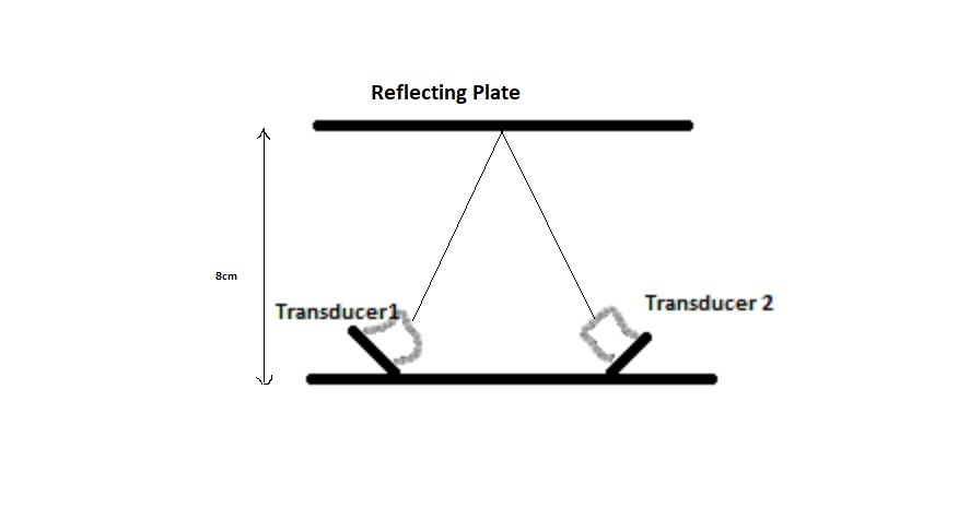
    Thanks for your reply. I tried using Murata MA58MF14-7N in the bi-static mode for short distance measurement, but it did not provide satisfactory results and it was able to measure distance above 18cm.  My application requirement is that I will transmit from a transducer connected with one PGA460 and after reflection from a plate at a distance of around 8 cm echo will have listened at another transducer connected to the second PGA460. The setup will be at an angle. Rough sketch of setup is shown below:

    So for initial evaluation, I am gonna use single BOOSTXL-PGA460 in bistatic mode. My main requirement is short range detection and I don't have any constraint on FOV. I require closed top transducer as my final product has an outdoor application and has to work in harsh conditions. If I want to proceed with MA300D1-1 what hardware changes do I have to make on BOOSTXL-PGA460 EVM?

    Thanks

    Nishant Sharma
  • Hi Akeem,

    I hope you could post your response, so I could proceed ahead with further evaluation.

    Thanks

    Nishant Sharma

  • Part Number: PGA460-Q1

    Hi,

    I mistakenly pressed "This resolved my issue" button on previous thread. So I am putting up a follow up question for the linked thread.

    I tried using Murata MA58MF14-7N in the bi-static mode for short distance measurement, but it did not provide satisfactory results and it was able to measure distance above 18cm.  My application requirement is that I will transmit from a transducer connected with one PGA460 and after reflection from a plate at a distance of around 8 cm echo will have listened at another transducer connected to the second PGA460. The setup will be at an angle. Rough sketch of setup is shown below:

    So for initial evaluation, I am gonna use single BOOSTXL-PGA460 in bistatic mode. My main requirement is short range detection and I don't have any constraint on FOV. I require closed top transducer as my final product has an outdoor application and has to work in harsh conditions. If I want to proceed with MA300D1-1 what hardware changes do I have to make on BOOSTXL-PGA460 EVM?

    Thanks

    Nishant Sharma

  • Hi Nishant,

    The hardware changes for the MA300D1-1 are the same as the MCUSD13A300B09RS transducer you initially tried:

    • Use a high frequency transformer (B78416A2386A003 is ok)
    • Remove the matching components in parallel to the transducer (C_Tune and R_Damp). You can add an R_Damp of 10kOhm to potentially improve short ranging performance even more.

    I am attaching an example register map you can use as a starting point for this transducer (assumes 9V supply).

    0245.GRID_USER_MEMSPACE-2017-05-26_143849.txt
    ;GRID_USER_MEMSPACE
    00 (USER_DATA1),00
    01 (USER_DATA2),00
    02 (USER_DATA3),00
    03 (USER_DATA4),00
    04 (USER_DATA5),00
    05 (USER_DATA6),00
    06 (USER_DATA7),00
    07 (USER_DATA8),00
    08 (USER_DATA9),00
    09 (USER_DATA10),00
    0A (USER_DATA11),00
    0B (USER_DATA12),00
    0C (USER_DATA13),00
    0D (USER_DATA14),00
    0E (USER_DATA15),00
    0F (USER_DATA16),00
    10 (USER_DATA17),00
    11 (USER_DATA18),00
    12 (USER_DATA19),00
    13 (USER_DATA20),00
    14 (TVGAIN0),88
    15 (TVGAIN1),88
    16 (TVGAIN2),88
    17 (TVGAIN3),00
    18 (TVGAIN4),00
    19 (TVGAIN5),00
    1A (TVGAIN6),01
    1B (INIT_GAIN),C0
    1C (FREQUENCY),64
    1D (DEADTIME),80
    1E (PULSE_P1),06
    1F (PULSE_P2),86
    20 (CURR_LIM_P1),15
    21 (CURR_LIM_P2),D5
    22 (REC_LENGTH),03
    23 (FREQ_DIAG),00
    24 (SAT_FDIAG_TH),EE
    25 (FVOLT_DEC),7C
    26 (DECPL_TEMP),0F
    27 (DSP_SCALE),00
    28 (TEMP_TRIM),00
    29 (P1_GAIN_CTRL),24
    2A (P2_GAIN_CTRL),00
    2B (EE_CRC),94
    40 (EE_CNTRL),00
    41 (BPF_A2_MSB),56
    42 (BPF_A2_LSB),72
    43 (BPF_A3_MSB),F3
    44 (BPF_A3_LSB),72
    45 (BPF_B1_MSB),06
    46 (BPF_B1_LSB),47
    47 (LPF_A2_MSB),7C
    48 (LPF_A2_LSB),D3
    49 (LPF_B1_MSB),01
    4A (LPF_B1_LSB),97
    4B (TEST_MUX),00
    4C (DEV_STAT0),80
    4D (DEV_STAT1),00
    5F (P1_THR_0),88
    60 (P1_THR_1),88
    61 (P1_THR_2),88
    62 (P1_THR_3),88
    63 (P1_THR_4),88
    64 (P1_THR_5),88
    65 (P1_THR_6),84
    66 (P1_THR_7),21
    67 (P1_THR_8),08
    68 (P1_THR_9),42
    69 (P1_THR_10),10
    6A (P1_THR_11),80
    6B (P1_THR_12),80
    6C (P1_THR_13),80
    6D (P1_THR_14),80
    6E (P1_THR_15),00
    6F (P2_THR_0),88
    70 (P2_THR_1),88
    71 (P2_THR_2),88
    72 (P2_THR_3),88
    73 (P2_THR_4),88
    74 (P2_THR_5),88
    75 (P2_THR_6),84
    76 (P2_THR_7),21
    77 (P2_THR_8),08
    78 (P2_THR_9),42
    79 (P2_THR_10),10
    7A (P2_THR_11),80
    7B (P2_THR_12),80
    7C (P2_THR_13),80
    7D (P2_THR_14),80
    7E (P2_THR_15),00
    7F (THR_CRC),28
    EOF
    

  • Hi Akeem,

    Thanks for the reply. I will use register map provided by you. Are you suggesting to use external 9V supply to drive the transducer? Will it not work with USB power supply? In the datasheet of MA300D1-1 it is stated that maximum input voltage is 50V peak to peak but when i was working with MA58MF14-7N the voltage applied by PGA460 EVM was 120V peak to peak as seen on scope. Will higher supply voltage harm the transducer? If so, how to proceed ahead. In anticipation of your early response.

    Thanks

    Nishant Sharma

  • Nishant,

    You can use the USB-boost supply for 7V center tap operation. With a 9V center tap, the driver current limit is reduced to 200mA to reduce the excitation voltage to <=50Vpp. Keep in mind that the driver current limit can be treated like an excitation voltage knob. When evaluating a new transducer or transformer, I always recommend to start with the lowest driver current limit of 50mA, and steadily increase the driver current limit until the oscilloscope monitored excitation voltage approaches the maximum peak to peak voltage rating of the transducer.

    For the MA300D1-1 specifically, I noticed that a lower center tap voltage (3.3V) with a larger driver current limit (450mA) resulted in a more ideal excitation sinusoidal waveform. However, this configuration would require a second supply voltage of 3.3V exclusively for the transformer center-tap.

  • Akeem,

    Thanks for you response and detailed explanation. I will proceed with USB supply while keeping driver current at around 50mA initially and increasing the driver current based on excitation voltage appearing on oscilloscope. I will receive my Murata MA300D1-1 transducer by coming Monday and start testing after that. Thanks for all the support and resolving my issues. 

    Thanks

    Nishant Sharma 

  • Hi Akeem,

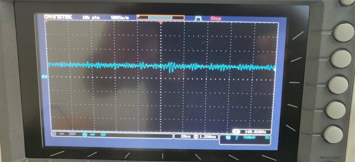
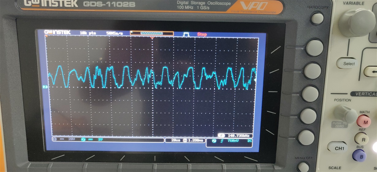
    I tried using your register configuration file with the MA300D1-1, but still there is a lot of noise and am not able to get any results. I am hereby attaching DSO captures of AFE output.

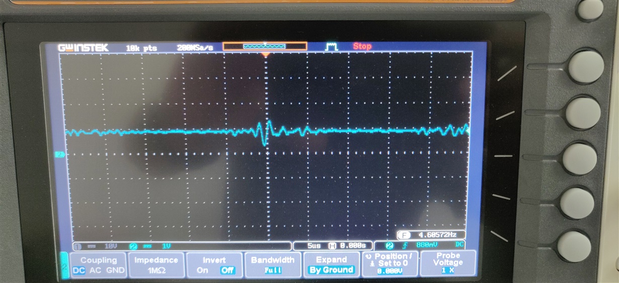
    This is the capture of AFE output on test pin when there is no command issued to the PGA460.

    This is the AFE output when listen only command is issued tp PGA460. 

    From these captures it seems that there is some inherent noise present at the AFE.

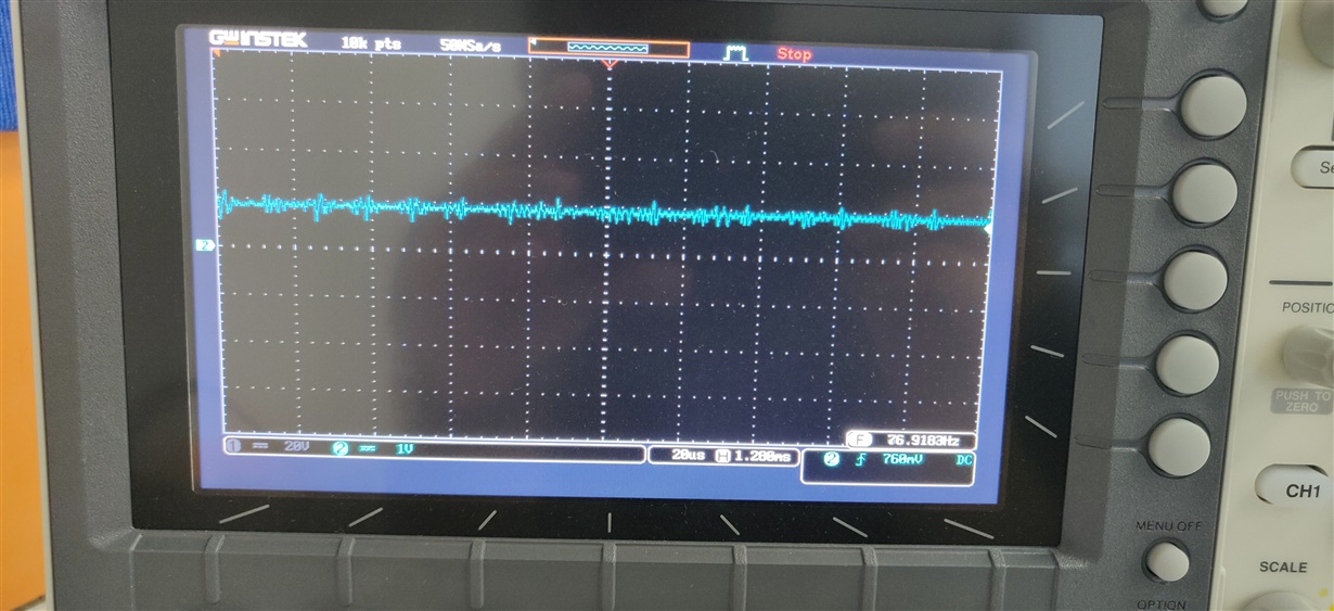
    When i tried to test MA58MF14-7N with different daughtercard there was no noise present at the AFE output. Scope capture is shown below:

    Can you explain what might be the cause of noise on 1st daughtercard which is being used with MA300D1-1. That is why  I have not been able to observe ecgho data dump, as there is persistent noise on AFE without even any command. My 2nd daughtercard equipped for driving 58.6KHz transducer is working fine.

    Thanks

    Nishant Sharma

  • Hi Nishant,

    The AFE capture of the first daughtercard using the MA300D1-1 transducer indicates that the XDCR+ and/or XDCR- terminal of the transducer is floating. When the transducer is properly connected, the AFE output should be DC idle biased to 0.9V as you are showing on the second daughtercard. XDCR+ should be connected to the path that eventually terminates at the INP pin of the device, and XDCR- should be grounded.

    Please confirm that you have connected/soldered the transducer properly (continuity test). Then start with a mono-static single transducer configuration (daughtercard's default mode) to ensure the driver and receiver are both working. Check all components of the XDCR+ to INP path to ensure they are not damaged from previous testing.

  • Hi Akeem,

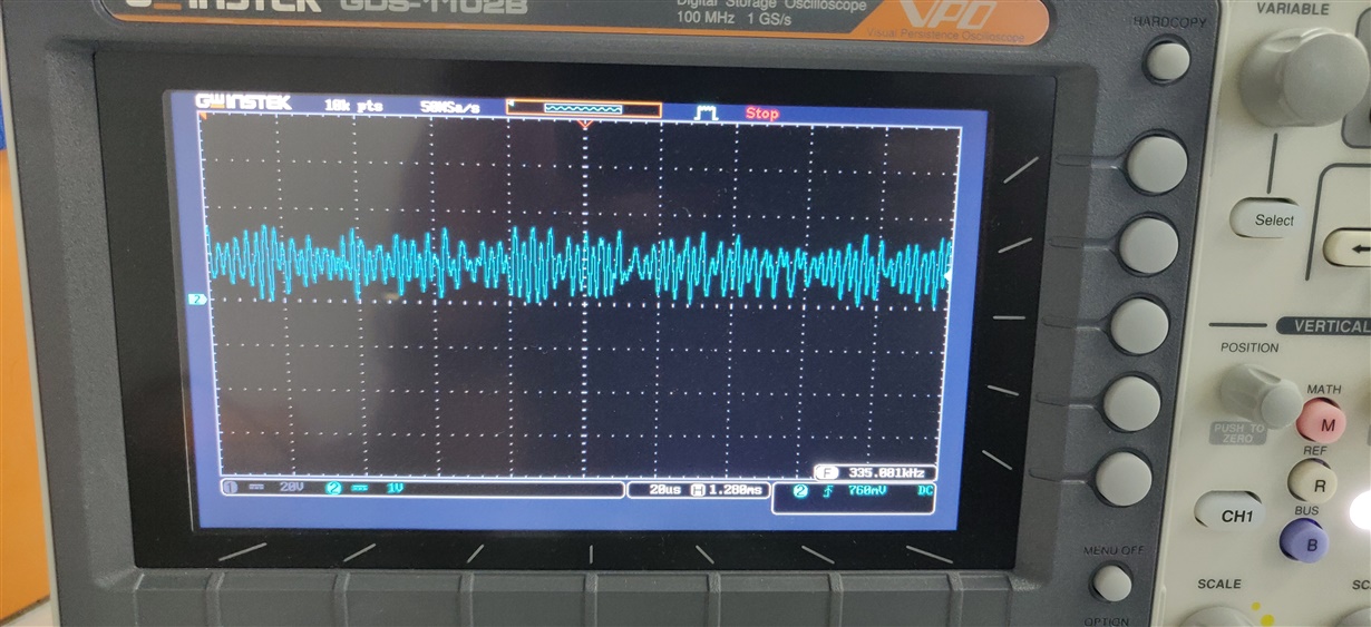
    I performed hardware debugging on my daughtercard and found no damaged components. The connections on both the daughtercards are same except for change of Transformer and removal of R38 and C15 on the one with MA300D1-1 transducer. Now I am completely confused about the status of AFE output state at different stages. I am attaching a series of DSO captures of AFE output as obtained on test pin.

    1. AFE output without connecting daughter card.

    2. AFE output captures with daughtercard optimized for Murata MA58MF14-7N (No burst or listen command is issued)

       (A). Transducer not connected to daughtercard

     (B) Transducer connected to daughtercard

    3.  AFE output captures with daughtercard optimized for Murata MA300D1-1 (No burst or listen command is issued)

      (A). Transducer not connected to daughtercard

    (B) Transducer connected to daughtercard

    It will be very helpful if you could explain me the state of AFE output at different times, so i could figure out whether there is a hardware issue with my EVM or daughtercard. Kindly shed the light on what might be cause for erroneous AFE output.  If you could share the captures of AFE output on your setup I could use them for reference and it can expedite the process of debugging.

    Thanks and Regards

    Nishant Sharma

  • Hi Akeem,

    I was hoping for a response to proceed ahead with my testing.

    Thanks and Regards

    Nishant Sharma

  • Hi Nishant,

    Akeem is out of office and will respond to your request next week. Meanwhile please take a look at the PGA460 product folder and also FAQ under PGA460. 

  • Hi Nishant,

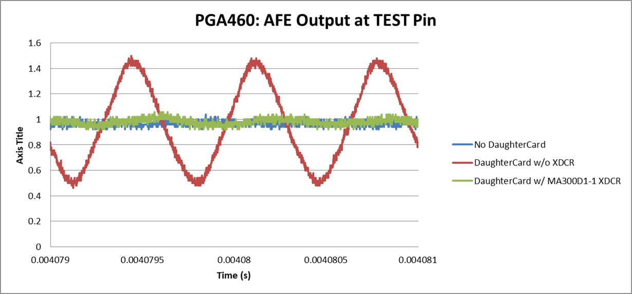
    I am attaching an oscilloscope capture collection of the AFE output at the TEST pin for your reference.

    The daughtercard conditions are as follows:

    • Transducer: MA300D1-1
    • Transformer: TDK/EPCOS B78416A2386A003
    • Mono-static mode
    • Removed R38 (R_damp) and C15 (Ctune)

  • Nishant,

    Please take a look at my latest post regarding the A2 coefficient of the high-frequency (180-480kHz) range. You may need to manually force the BPF_A2_MSB and _LSB values for your high-frequency evaluation. Refer to the look-up table in the post to find the A2 coefficient in hex with regard to frequency.

  • Hi Akeem,

    Can you post the link for the above mentioned post.

    Thanks and Regards

    Nishant Sharma

  • Nishant,

    Re-posting link to the post "PGA460: Frequency offset in high frequency mode":

    https://e2e.ti.com/support/sensors/f/1023/p/819254/3042704#3042704