This thread has been locked.

If you have a related question, please click the "Ask a related question" button in the top right corner. The newly created question will be automatically linked to this question.

PGA460-Q1: Interfaced to Arduino Uno_source code

Part Number: PGA460
Other Parts Discussed in Thread: , ENERGIA, MSP430F5529

Hi,

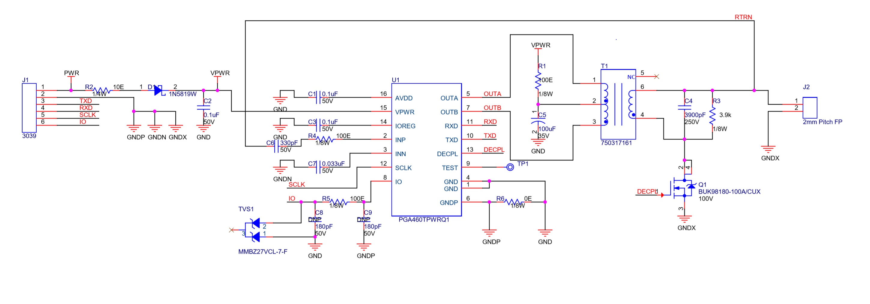
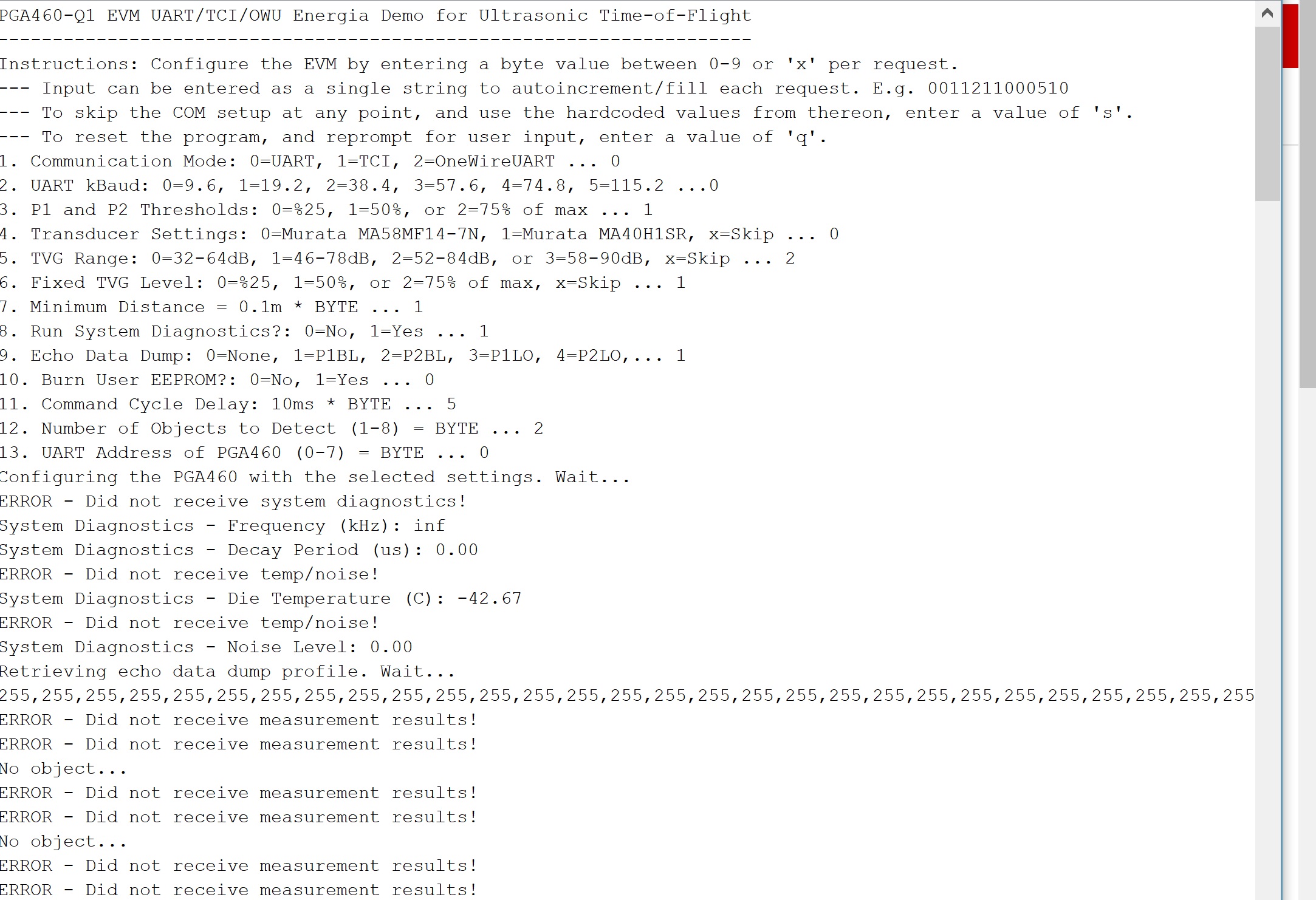
    Could you please share me the arduino source code for interfacing the PGA460-Q1.I have designed and developed the ultrasonic sensor module using PGA460-Q1 driver IC and Murata sensor.I would like to inteface this sensor with arduino uno for getting the distance information.Please provide the suitable source code for this 

Thanks & regards

Sreejith S V

  • Hi Sreejith,

    For PGA460 software development, I recommend that you start with the PGA460 Software Development Guide and PGA460 Energia Library and Code Example downloads. These will help guide you with USART (UART and SPI) specific examples for the Energia and Arduino microcontroller kits.

    For information on the general structure of the USART packet, refer to section "7.3.6.2.1 USART Asynchronous Mode" of  the datasheet: http://www.ti.com/lit/ds/symlink/pga460-q1.pdf. Note the non-default 2-stop bit requirement for the UART configuration.

  • Thanks Akeem for your quick response.Will go through these documents and get back to you if any support is required for the same.

    Thanks & Regards

    Sreejith

  • I just gone through the document and tried to compile the code using arduino id,getting so many errors.I solved  most of the errors,but still there is some errors related to the library functions.Could you please share me the modified code which is suitable for arduino ide and arduino controller.My actual aim is to get the distance data from the sensor via one wire communication using arduino .Sensor board is ready with pga460 and murata sensor.

  • I just gone through the document and tried to compile the code using arduino id,getting so many errors.I solved  most of the errors,but still there is some errors related to the library functions.Could you please share me the modified code which is suitable for arduino ide and arduino controller.My actual aim is to get the distance data from the sensor via one wire communication using arduino .Sensor board is ready with pga460 and murata sensor.

  • Hi Sreejith,

    Does Arduino Uno support Serial1? The code uses two serial ports: one for serial communication to the PC, and the other for serial/UART communication to the PGA460.

    To get the PGA460 Energia library to run in Arduino Mega:

    1) Delete the following from the PGA460EnergiaLibrary_vx.x.x library folder: "PGA460_SPI.cpp", "PGA460_SPI.h", "utility" folder. The SPI functions for the PGA460 were customized specifically for the MSP430F5529 microcontroller. SPI support is only enabled through Energia, not Arduino at this time.

    2) Replace all instances of #include <Energia.h> to #include <Arduino.h> in the library files (PGA40_USSC.h/.cpp)

    3) In all files, change any reference of "PUSH2", "GREEN_LED", "RED_LED" to a Arduino pin numbers. These designators are specific to the Energia.h file for the LaunchPads.

    4) Delete case 3 from the initBoostXLPGA460 function in PGA460_USSC.cpp.

  • Hi Akeem,

                      Thanks for your reply.I already solved the issues by studying the code and modified for  Arduino IDE.Successfully compiled for Arduino Mega .My sensor PCB fabrication is in progress and after getting it assembled will test this code using arduino mega and sensor board.Will let you post the status.

    Can I interface multiple sensor using the same code and what will be the interface for multiple sensor interface?

    My assumption is by changing the address we can interface multiple sensors using one wire interface.For that I need to connect serial to onewire transceiver chip in between arduino serial and sensor board and connect all the sensor boards IO line to transceiver output?Is this correct,Please let me know

    Thanks

    Sreejith

  • Hi Sreejith,

    The PGA460 offers four different interfaces: UART, SPI, OWU, and TCI

    OWU and TCI are automotive interfaces referenced to high-level battery. In this case you would need a transceiver to level shift from VPWR (i.e. 12V) to 5V for a logic high.If your application is not automotive, I recommend that you use UART or SPI so you can directly interface the PGA460 to the Arduino without the need for a transceiver. UART/SPI is much easier to work with anyway.

    Because the PGA460 has a three-bit software address (UART_ADDR), you can have up to eight PGA460s on the same UART or SPI bus. Refer to PGA460 FAQ #4.4.11 (http://www.ti.com/lit/pdf/slaa733) for details on auto-addressing:

    4.4.11 Is daisy-chain supported by the PGA460? Can the master controller automatically differentiate and program the PGA460 UART address? Daisy-chain auto-addressing and automatic slave node position detection (SNPD) are not supported by the PGA460. External hardware or switches must be used in combination with the external master controller to automatically assign address to multiple PGA460 devices connected to the same bus. The example provided is interchangeable for the IO and TX pin. When switching IO, be sure select a bidirectional switch rated for VPWR (up to 30 V). The TX pin is a unidirectional pin rated at either 3.3V (default) or 5.0 V.

  • Hi Akeem,

                   My PGA460 with sensor board is now ready and started testing using arduino mega.I connected the TXD and RXD pins to RX0 and TX0 of arduino mega and supplied 12VDC power input.But the sensor is not responding.I have attached my schematic and arduino serial monitor screen shots.Please check and advice for troubleshooting the same

    Regards

    Sreejith

  • Hi Akeem,

                        I have solved the issues and getting the object distance data from the sensor.The following are the issues

    1)I am using 5V micro so need to connect 100k pull up to 5V

    2) UART Communication port required in Arduino is TX1 and RX1 

    3) Required to enable the temperature compensation register bit else remove the mosfet and connect ground  to transformer secondary pin 4

    Could you please suggest me  the actual configuration required for my hardware and the meaning of the red marked configurations .I am using  Murata MA58MF14-7N sensor

    1. Communication Mode: 0=UART, 1=TCI, 2=OneWireUART ... 0
    2. UART kBaud: 0=9.6, 1=19.2, 2=38.4, 3=57.6, 4=74.8, 5=115.2 ...0
    3. P1 and P2 Thresholds: 0=%25, 1=50%, or 2=75% of max ... ?
    4. Transducer Settings: 0=Murata MA58MF14-7N, 1=Murata MA40H1SR, x=Skip ... 0
    5. TVG Range: 0=32-64dB, 1=46-78dB, 2=52-84dB, or 3=58-90dB, x=Skip ...?
    6. Fixed TVG Level: 0=%25, 1=50%, or 2=75% of max, x=Skip ... ?
    7. Minimum Distance = 0.1m * BYTE ... ?
    8. Run System Diagnostics?: 0=No, 1=Yes ... 0
    9. Echo Data Dump: 0=None, 1=P1BL, 2=P2BL, 3=P1LO, 4=P2LO,... ?
    10. Burn User EEPROM?: 0=No, 1=Yes ... ?
    11. Command Cycle Delay: 10ms * BYTE ... ?
    12. Number of Objects to Detect (1-8) = BYTE ... 1
    13. UART Address of PGA460 (0-7) = BYTE ... 0

    Regards

    Sreejith

  • Part Number: PGA460

    Hi

      I am also getting the same ultrasonic readings with or without objects present.Switching on and off the power supply will sometimes give a different measurement number. Please provide the suitable solution for this.

    I am using arduino mega 2560 and Murata MA58MF14-7N transducer.

    Regards

    Sreejith

  • Hi Sreejith,

    To help debug your problem, please provide:

    • Your PGA460 EEPROM register values before and after sending a burst/listen command.
    • The ultrasonic measurement results for at least one object
    • The echo data dump for at least one measurement

    Send these items for before and after power cycling.

  • Sreejith,

    Your items marked in red can be described as follows (from the PGA460_USSC.cpp file of the PGA460 Energia Library and Code Example download).

    If you do not have pre-determined PGA460 EEPROM register values from EVM-GUI evaluation, use the mid-code values for the threshold and TVG settings as a starting point.

    Item #3:

    /*------------------------------------------------- initThresholds -----

    | Function initThresholds
    |
    | Purpose: Updates threshold mapping for both presets, and performs bulk threshold write
    |
    | Parameters:
    | thr (IN) -- updates all threshold levels to a fixed level based on specific percentage of the maximum level.
    | All times are mid-code (1.4ms intervals).
    | Modify existing case statements, or append additional case-statement for custom user threshold configurations.
    | • 0 = 25% Levels 64 of 255
    | • 1 = 50% Levels 128 of 255
    | • 2 = 75% Levels 192 of 255
    |
    | Returns: none
    *-------------------------------------------------------------------*/

    Item # 5&6:

    /*------------------------------------------------- initTVG -----
    | Function initTVG
    |
    | Purpose: Updates time varying gain (TVG) range and mapping, and performs bulk TVG write
    |
    | Parameters:
    | agr (IN) -- updates the analog gain range for the TVG.
    | • 0 = 32-64dB
    | • 1 = 46-78dB
    | • 2 = 52-84dB
    | • 3 = 58-90dB
    | tvg (IN) -- updates all TVG levels to a fixed level based on specific percentage of the maximum level.
    | All times are mid-code (2.4ms intervals).
    | Modify existing case statements, or append additional case-statement for custom user TVG configurations
    | • 0 = 25% Levels of range
    | • 1 = 50% Levels of range
    | • 2 = 75% Levels of range
    |
    | Returns: none
    *-------------------------------------------------------------------*/

    Item #7:

    The Energia program will ignore any objects read as less than the minimum distance value in increments of 10cm. Set to a value of '0' to disable this master controller very short distance mask. This was put in place in the event the burst-and/or-decay signature triggered the threshold capture.

    Item#9:

    /*------------------------------------------------- runEchoDataDump -----
    | Function runEchoDataDump
    |
    | Purpose: Runs a preset 1 or 2 burst and or listen command to capture 128 bytes of echo data dump.
    | Toggle echo data dump enable bit to enable/disable echo data dump mode.
    |
    | Parameters:
    | preset (IN) -- determines which preset command is run:
    | • 0 = Preset 1 Burst + Listen command
    | • 1 = Preset 2 Burst + Listen command
    | • 2 = Preset 1 Listen Only command
    | • 3 = Preset 2 Listen Only command
    | • 17 = Preset 1 Burst + Listen broadcast command
    | • 18 = Preset 2 Burst + Listen broadcast command
    | • 19 = Preset 1 Listen Only broadcast command
    | • 20 = Preset 2 Listen Only broadcast command
    |
    | Returns: none
    *-------------------------------------------------------------------*/

    Item #10:

    /*------------------------------------------------- burnEEPROM -----
    | Function burnEEPROM
    |
    | Purpose: Burns the EEPROM to preserve the working/shadow register values to EEPROM after power
    | cycling the PGA460 device. Returns EE_PGRM_OK bit to determine if EEPROM burn was successful.
    |
    | Parameters:
    | none
    |
    | Returns: bool representation of EEPROM program success
    *-------------------------------------------------------------------*/

    Item #11:

    The amount of time between each burst/listen command as the Energia program loops on the master controller. Can be set in delay intervals of 10ms multipliers.

  • Thanks Akeem for your detailed description.Now I am receiving object distance and which varying with various configuration settings.

    But now the problem is  , I am always getting the same ultrasonic readings with or without objects present.Switching on and off the power supply will sometimes give a different measurement number. Please provide the suitable solution for this.

    Please find the following sample object detection results and configuration settings.

    Configuration  

    1.Communication Mode: 0=UART, 1=TCI, 2=OneWireUART ... 0
    2. UART kBaud: 0=9.6, 1=19.2, 2=38.4, 3=57.6, 4=74.8, 5=115.2 ...1
    3. P1 and P2 Thresholds: 0=%25, 1=50%, or 2=75% of max ... 0
    4. Transducer Settings: 0=Murata MA58MF14-7N, 1=Murata MA40H1SR, x=Skip ... 0
    5. TVG Range: 0=32-64dB, 1=46-78dB, 2=52-84dB, or 3=58-90dB, x=Skip ... 2
    6. Fixed TVG Level: 0=%25, 1=50%, or 2=75% of max, x=Skip ... 1
    7. Minimum Distance = 0.1m * BYTE ... 1
    8. Run System Diagnostics?: 0=No, 1=Yes ... 1
    9. Echo Data Dump: 0=None, 1=P1BL, 2=P2BL, 3=P1LO, 4=P2LO,... 0
    10. Burn User EEPROM?: 0=No, 1=Yes ... 0
    11. Command Cycle Delay: 10ms * BYTE ... 5
    12. Number of Objects to Detect (1-8) = BYTE ... 8
    13. UART Address of PGA460 (0-7) = BYTE ... 0

    Initial Result

    P1 Obj1 Distance (m): 8.90
    P1 Obj2 Distance (m): 1.00
    P1 Obj3 Distance (m): 10.49
    P1 Obj4 Distance (m): 7.50
    P1 Obj5 Distance (m): 11.14
    P1 Obj6 Distance (m): 9.56
    P1 Obj7 Distance (m): 10.50
    P1 Obj8 Distance (m): 0.90

    After one power cycle result

    P1 Obj1 Distance (m): 9.61
    P1 Obj2 Distance (m): 2.40
    P1 Obj3 Distance (m): 10.48
    P1 Obj4 Distance (m): 7.67
    P1 Obj5 Distance (m): 11.14
    P1 Obj6 Distance (m): 9.56
    P1 Obj7 Distance (m): 10.50
    P1 Obj8 Distance (m): 0.90


    Regards

    Sreejith

  • Hi Akeem,

                       Thanks for your reply.Please let me know how to get these values (EEPROM register& echo data dump),because I am using arduino mega & arduino IDE for running the main code and getting only the distance information on the serial monitor.

    Regards

    Sreejith

  • Thanks Akeem .

    Now the problem is always getting same value,till each power turn ON/OFF cycle and the EEPROM write showing always failure

    Regards

    Sreejith

  • Sreejith,

    How many objects are you trying to detect per capture? You are printing the maximum number of objects the PGA460 can report, which is 8. Regardless, the results are invalid because the distance values should always be ascending for multiple objects in a single capture.

    Here are your results:

    Initial result After one power cycle result

    P1 Obj1 Distance (m): 8.90
    P1 Obj2 Distance (m): 1.00
    P1 Obj3 Distance (m): 10.49
    P1 Obj4 Distance (m): 7.50
    P1 Obj5 Distance (m): 11.14
    P1 Obj6 Distance (m): 9.56
    P1 Obj7 Distance (m): 10.50
    P1 Obj8 Distance (m): 0.90

    P1 Obj1 Distance (m): 9.61
    P1 Obj2 Distance (m): 2.40
    P1 Obj3 Distance (m): 10.48
    P1 Obj4 Distance (m): 7.67
    P1 Obj5 Distance (m): 11.14
    P1 Obj6 Distance (m): 9.56
    P1 Obj7 Distance (m): 10.50
    P1 Obj8 Distance (m): 0.90

    A correct representation of the output should appear as:

    Initial result
    P1 Obj1 Distance (m): 0.90
    P1 Obj2 Distance (m): 1.00
    P1 Obj3 Distance (m): 7.50
    P1 Obj4 Distance (m): 8.00
    P1 Obj5 Distance (m): 8.90
    P1 Obj6 Distance (m): 9.56
    P1 Obj7 Distance (m): 10.49
    P1 Obj8 Distance (m): 10.50

    A few things to check:

    1. What are the raw time-of-flight values? There may be an offset to the elements in the ultrasonic measurement results array, which is why your results appear erroneous when converting from time-of-flight to distance. For instructions on reporting the raw ultrasonic measurement result values see the related post: https://e2e.ti.com/support/sensors/f/1023/p/849269/3142148#3142148
    2. To readout the echo data dump values, set input option #9 to 1 or 2 depending on which preset you want to observe: Echo Data Dump: 0=None, 1=P1BL, 2=P2BL, 3=P1LO, 4=P2LO,... (1 or 2)3
    3. Without a transducer connected, do your results change?

  • Thanks Akeem for your reply.Please find the following result

    1. What are the raw time-of-flight values? There may be an offset to the elements in the ultrasonic measurement results array, which is why your results appear erroneous when converting from time-of-flight to distance.

    Result ,after changing the library code like this

    case 0: //Obj1 Distance (m)
    {
         objDist = (ultraMeasResult[1]<<8) + ultraMeasResult[2];
         objReturn = objDist; // SKIP TOF to DISTANCE CONVERSION //(objDist/2*0.000001*speedSound) - digitalDelay;
         break;
    }

    9. Echo Data Dump: 0=None, 1=P1BL, 2=P2BL, 3=P1LO, 4=P2LO,... 2
    10. Burn User EEPROM?: 0=No, 1=Yes ... 0
    11. Command Cycle Delay: 10ms * BYTE ... 5
    12. Number of Objects to Detect (1-8) = BYTE ... 8
    13. UART Address of PGA460 (0-7) = BYTE ... 0
    Configuring the PGA460 with the selected settings. Wait...
    System Diagnostics - Frequency (kHz): 16.81
    System Diagnostics - Decay Period (us): 1232.00
    System Diagnostics - Die Temperature (C): -30.00
    System Diagnostics - Noise Level: 71.00
    Retrieving echo data dump profile. Wait...
    255,220,55,61,183,246,63,191,191,191,191,191,191,191,191,191,191,191,191,191,87,87,87,61,183,246,63,251,48,247,187,175,83,83,166,198,208,27,131,191,191,182,182,135,139,139,191,199,183,36,182,57,208,192,47,71,102,207,218,168,59,199,62,214,247,195,246,199,75,176,91,51,107,174,235,231,172,107,194,43,54,185,167,56,190,211,203,3,211,59,75,67,174,53,163,167,215,208,59,231,246,27,246,71,215,11,99,192,187,226,61,209,251,32,59,211,147,215,183,191,191,35,115,247,218,59,61,134,
    P1 Obj2 Distance (m): 1.41
    P1 Obj6 Distance (m): 7.48
    P1 Obj7 Distance (m): 1.41
    P1 Obj8 Distance (m): 7.01
    P1 Obj2 Distance (m): 1.41
    P1 Obj6 Distance (m): 7.48
    P1 Obj7 Distance (m): 1.41
    P1 Obj8 Distance (m): 7.01
    P1 Obj2 Distance (m): 1.41
    P1 Obj6 Distance (m): 7.48
    P1 Obj7 Distance (m): 1.41

    1. To readout the echo data dump values, set input option #9 to 1 or 2 depending on which preset you want to observe: Echo Data Dump: 0=None, 1=P1BL, 2=P2BL, 3=P1LO, 4=P2LO,... (1 or 2)3

    9. Echo Data Dump: 0=None, 1=P1BL, 2=P2BL, 3=P1LO, 4=P2LO,... 2
    10. Burn User EEPROM?: 0=No, 1=Yes ... 0
    11. Command Cycle Delay: 10ms * BYTE ... 5
    12. Number of Objects to Detect (1-8) = BYTE ... 8
    13. UART Address of PGA460 (0-7) = BYTE ... 0
    Configuring the PGA460 with the selected settings. Wait...
    System Diagnostics - Frequency (kHz): 16.81
    System Diagnostics - Decay Period (us): 1232.00
    System Diagnostics - Die Temperature (C): -30.00
    System Diagnostics - Noise Level: 77.00
    Retrieving echo data dump profile. Wait...
    255,220,55,61,183,246,63,191,191,191,191,191,191,191,191,191,191,191,191,191,87,87,87,61,183,246,63,251,48,247,187,175,83,83,166,198,208,27,131,191,191,182,182,135,171,139,191,203,179,36,187,41,248,192,47,71,102,215,222,169,59,199,58,150,206,195,246,231,75,160,123,51,107,46,235,231,172,75,196,47,54,185,167,56,190,211,203,160,211,59,75,67,174,53,163,167,215,208,59,230,247,27,246,71,61,11,99,196,59,226,61,213,251,32,187,211,147,215,183,191,251,35,115,199,206,246,63,134,
    P1 Obj1 Distance (m): 5.98
    P1 Obj2 Distance (m): 1.41
    P1 Obj6 Distance (m): 7.48
    P1 Obj7 Distance (m): 1.41
    P1 Obj8 Distance (m): 7.01
    P1 Obj1 Distance (m): 5.98
    P1 Obj2 Distance (m): 1.41
    P1 Obj6 Distance (m): 7.48

    1. Without a transducer connected, do your results change?

    Without sensor ,result

    9. Echo Data Dump: 0=None, 1=P1BL, 2=P2BL, 3=P1LO, 4=P2LO,... 2
    10. Burn User EEPROM?: 0=No, 1=Yes ... 0
    11. Command Cycle Delay: 10ms * BYTE ... 5
    12. Number of Objects to Detect (1-8) = BYTE ... 8
    13. UART Address of PGA460 (0-7) = BYTE ... 0
    Configuring the PGA460 with the selected settings. Wait...
    System Diagnostics - Frequency (kHz): 16.81
    System Diagnostics - Decay Period (us): 1232.00
    System Diagnostics - Die Temperature (C): -30.00
    System Diagnostics - Noise Level: 70.00
    Retrieving echo data dump profile. Wait...
    255,220,55,61,183,246,63,191,191,191,191,191,191,191,191,191,191,191,191,191,87,87,87,61,183,246,63,251,48,247,187,175,83,83,166,198,208,27,131,191,191,182,182,135,139,155,191,235,179,36,187,185,208,192,47,7,102,207,222,168,59,199,58,150,47,207,246,230,75,176,123,51,107,46,235,230,44,107,226,234,38,185,167,56,190,211,203,3,249,59,203,67,174,53,163,167,215,240,59,230,246,27,246,71,61,11,99,196,187,226,61,209,251,32,63,211,147,215,57,195,191,35,115,247,206,246,61,134,
    P1 Obj1 Distance (m): 5.98
    P1 Obj2 Distance (m): 1.41
    P1 Obj6 Distance (m): 7.48
    P1 Obj7 Distance (m): 1.41
    P1 Obj8 Distance (m): 7.01
    P1 Obj1 Distance (m): 5.98
    P1 Obj2 Distance (m): 1.41

    After One power cycle result (Without sensor)

    P1 Obj1 Distance (m): 8.90
    P1 Obj2 Distance (m): 0.91
    P1 Obj3 Distance (m): 10.49
    P1 Obj4 Distance (m): 7.50
    P1 Obj5 Distance (m): 11.14
    P1 Obj6 Distance (m): 10.96
    P1 Obj7 Distance (m): 10.42
    P1 Obj8 Distance (m): 0.29

    Regards

    Sreejith

  • After changing the library code for 8 objects,received the following result

    Retrieving echo data dump profile. Wait...
    255,220,55,61,183,246,63,191,191,191,191,191,191,191,191,191,191,191,191,191,87,87,87,61,183,246,63,251,48,247,187,175,83,83,166,198,208,27,131,191,191,182,182,135,139,155,175,203,179,38,246,185,240,192,175,71,102,207,218,168,59,199,62,169,231,215,246,231,75,32,123,179,107,46,235,231,172,75,226,234,38,185,167,247,190,211,203,160,211,59,75,67,174,53,131,167,215,240,59,231,246,27,246,71,189,11,99,196,59,226,61,209,251,32,59,211,147,215,183,191,191,35,115,247,222,246,63,134,
    Error reading measurement results...Error reading measurement results...Error reading measurement results...No object...
    Error reading measurement results...Error reading measurement results...Error reading measurement results...No object...

  • Hi Akeem,

                     Please advise me based on the above results and help me for releasing the beta version of my ultrasonic sensor module.

    Could you please let me know your availability and convenient time for call to discuss and solve the issues of my sensor initial PoC version.

    Regards

    Sreejith

  • Waiting for your reply.

    Regards

    Sreejith

  • Hi Sreejith,

    My recommended approach to debugging this is to use a digital logic analyzer to first capture the physical UART TXD and RXD signals to ensure your Arduino is properly transmitting the expected UART packets, as well as validating that the device is responding with data correctly. None of your results appear correct, which leads me to believe there is some offset to the UART array of elements captured, or your UART port is not configured properly on the Arduino.

    Rather than using the PGA460 Energia Library functions, here is an example of a raw UART command implementation. Try running this example to determine if the PGA460 is receiving the master transmitted commands by probing your transducer's positive terminal to check for burst excitation. Note, this barebones code does not yet include terminal capture of the response from command 5 (ultrasonic measurement result), but will allow you to probe the UART TXD and RXD pins to determine if there is a valid device response (via a logic analyzer / oscilloscope):

    //note: bare bones raw UART demo used to send a burst/listen command to PGA460
    
    //cmd 0 - p1 burst listen
    byte buf0[4] = {0x55, 0x00, 0x01, 0xFE};
    //cmd 1 - p2 burst listen
    byte buf1[4] = {0x55, 0x01, 0x01, 0xFD};
    //cmd 5 - ultrasonic measurement (assume UART_ADDR=0)
    byte buf5[4] = {0x55, 0x05, 0xFA};
    //cmd 10 - register write decple to time of 4.096ms
    byte buf10[5] = {0x55, 0x0A, 0x26, 0x00, 0xCF};
    //cmd 17 - broadcast p1 burst listen
    byte buf17[4] = {0x55, 0x11, 0x01, 0xED};
    //cmd 19 - broadcast p1 listen only
    byte buf19[4] = {0x55, 0x13, 0x01, 0xEB};
    //cmd 25 - broadcast bulk threshold write
    byte buf25[35] =  {0x55, 0x19, 0x88, 0x88, 0x88, 0x88, 0x88, 0x88, 0x84, 0x21, 0x08, 0x42, 0x10, 0x80, 0x80, 0x80, 0x80, 0x00, 0x88, 0x88, 0x88, 0x88, 0x88, 0x88, 0x84, 0x21, 0x08, 0x42, 0x10, 0x80, 0x80, 0x80, 0x80, 0x00, 0x7C};
    
    const int buttonPin = PUSH2;     // the number of the pushbutton pin
    const int ledPin = RED_LED;      // the number of the LED pin
    int buttonState = 0;         // variable for reading the pushbutton status
    
    void setup() { 
    
      pinMode(ledPin, OUTPUT);
      pinMode(buttonPin, INPUT_PULLUP);
      delay(1000);
      
      // put your setup code here, to run once:
      Serial1.begin(19200);  // initialize PGA460 UART serial channel
      delay(1000);
    
      //assume UART_ADDR=0
      //bulk threshold write mid-code values to clear THR_CRC_ERR
      Serial1.write(buf25, sizeof(buf25));
      delay(100);
    
      // [TODO] set p1 rec length to 4.096ms
      
      // set UART_ADDR=0's time decouple to 4.096ms
      Serial1.write(buf10, sizeof(buf10));
      delay(100);
    }
    
    void loop() {
        // put your main code here, to run repeatedly: 
      
        // check if the pushbutton is pressed.
        while (digitalRead(buttonPin) == HIGH){}
        
        // broadcast p1 burst+listen (non-dependent on UART_ADDR)
        Serial1.write(buf17, sizeof(buf17));
        
        // delay by 100ms
        delay(100);
    
        //[TODO] print ultrasonic measurement results on terminal
        // read back ultrasonic meas results from UART_ADDR=0
        Serial1.write(buf5, sizeof(buf5));
      
        // toggle red LED
        digitalWrite(ledPin, !(digitalRead(ledPin)));   // turn the LED on (HIGH is the voltage level)
    
        // repeat loop every second
        delay (1000);      
    }

  • Thanks Akeem.

     Will do the debugging ,as suggested and let you update the result

    Regards

    Sreejith

  • Hi Akeem,

                        Please find the following test result while running the bare bones raw UART demo code.please check and let me know your suggestions.

    Sensor Positive terminal waveform

    UART TX & RX waveform

    Regards

    Sreejith

  • Sreejith,

    Thanks for probing the XDCR+ and UART signals. This confirms that the device is bursting the transducer, and the communication is intact. The only issue I see is that the blue UART waveform (I assume this is the PGA460-TXD pin) is idle low at some points. I recommend that you add a weak pull-up resistor (10k or 22kOhm) to the PGA460-TXD pin to ensure this pin is always idle high. This may explain why some of your received data doesn't translate correctly.

    In a typical UART system, the slave device should idle high the TXD pin; however, the PGA460 shares both SPI and UART functionality at the TXD and RXD pins, so it is in tri-state by default, which is why you should try adding an external resistor pull-up. You can also try configuring your mastercontroller's UART-RXD pin as an input with a pull-up to achieve a similar result.

  • Excellent Akeem.Now the sensor is working .I have put 10k pull up in the master RX side.I am still working on this sensor to achieve long range and multiple objects.Will let you update and ask support if required

    Thanks a lot Akeem.

    Regards

    Sreejith

  • Hi Akeem

                     I am unable to get the object distance more than 1m. I have tried several options but still getting the distance up to 1m.Please advice me for the same

    Regards

    Sreejith

  • Sreejith,

    Send me a copy of your memory map configuration (bulk EEPROM read - UART command 11), and the three outputs of your echo data dump (UART command 7) when an object is at 30cm, 50cm, and 1m. This will help me debug why you cannot detect object beyond 1m.