This thread has been locked.

If you have a related question, please click the "Ask a related question" button in the top right corner. The newly created question will be automatically linked to this question.

[FAQ] Software related queries based on mmWave SDK

Other Parts Discussed in Thread: AWR1642, AWR1843, AWR6843, AWR2944, UNIFLASH, SYSCONFIG, AWR2243, AM2732, AWR1243

⇐ Back to Main FAQ Thread :   [FAQ] PLEASE READ : mmWave Forum Guidelines and FAQ Thread


This Thread  addresses FAQ in context of  mmWave SDK (SW) ,  Features add on or tweaks to Demo codes (or Labs)


Q1. How to create a new mmwave sensor project from scratch [Project0]?

Answer: Please refer this thread- https://e2e.ti.com/support/tools/ccs/f/81/t/836333


Q2. How to find root-cause if a device goes into fault at DSS/BSS end OR how to find if a device is in fault/bad state?

       How to decode the error value mmWave library throws at the application level?

Answer: mmw demo from mmWave SDK checks application status or return values of a function to find out device health and goes into ASSERT if something wrong. Error at DSS is communicated to MSS which says the source code line no. for user to find out root cause.

If BSS goes into some error state or fault then it sends CPU/ESM/Analog Fault asynchronous event [RL_RF_AE_CPUFAULT_SB, RL_RF_AE_ESMFAULT_SB, RL_RF_AE_ANALOG_FAULT_SB] to MSS, MSS application needs to handle these fault. Most of the time recovery from these faults is to reset the device. It can be done by an external processor (notify over nError-out), internal Watchdog, External Watchdog.

At most of the error points, mmw demo sets errCode from the function (like mmwave library) which contains the cause of error.

[bit 31:16] - mmWave Error : MMWAVE_EINVAL to MMWAVE_EINVALIDCALMONUNIT (mmwave.h)

[bit 15:2] - sub system Error : It can be from DSS or BSS, For BSS error codes are defined in mmwavelink.h 'RL_RET_CODE_***'

[bit 1:0] - error level : MMWave_ErrorLevel

 Q3. How to send custom user data or intermediate FFT processing data over LVDS?

Answer: Refer related threads-

https://e2e.ti.com/support/sensors/f/1023/p/758435/2803488

https://e2e.ti.com/support/sensors/f/1023/t/759979

Q4. How much time does SBL take to boot up and time to switch to the application?

Answer: Boot up time of SBL depends on the size of SBL image which PBL (primary bootloader) takes to copy content from sFlash to RAM. Default SBL in the SDK takes around 35msec to bootup (measured from nRST: device reset) and SBL to application (mmw demo from SDK 2.1) boot takes around 65mSec. Again these two times vary based on image size.

Here is similar e2e thread https://e2e.ti.com/support/sensors/f/1023/p/767876/2838860#2838860


Q5. What is the format of the data mmw demo sends out over UART?

Format of object data out from application may differ based on SDK version and for different application. These links will explain the basic format of that, most of TI-Rex application provides output data format in their user/developer user guide document.

/cfs-file/__key/communityserver-discussions-components-files/1023/mmw-Demo-Data-Structure_5F00_8_5F00_16.pdf

https://e2e.ti.com/support/sensors/f/1023/t/753460

Even after this you don't find exact output format of any of mmwave sensor application, then you need to dive into source code. DSS generates the object data packet, copies to HSRAM and sends to MSS which further sends it over UART/CAN interface. Look for function having string 'sendProcessOutputToMSS' or 'sendResult' in dss_main.c (most of the application uses similar function name), now you can backtrace to find the packet format.


Q6. Implement the watchdog feature with mmw demo application

Answer: At this thread, code snippet is provided to implement the watchdog feature to mmw demo-

https://e2e.ti.com/support/tools/ccs/f/81/p/835932/3091964#3091964


Q7. How to get input from CCS console?

Answer: Many of times while application development, we need to take input from CCS GUI only. Refer these threads to do that:

https://e2e.ti.com/support/sensors/f/1023/p/838177/3099822#3099822

https://e2e.ti.com/support/microcontrollers/msp430/f/166/t/439318?Scanf-in-CCS-for-MSP430

Q8. How to add sFlash feature in the mmw demo or any other mmwave application?

Please refer this application note- http://www.ti.com/lit/an/swra583/swra583.pdf

Q9. How do I reset the device from the application itself?

You can use the internal watchdog feature to reset the device, refer this thread to implement the watchdog in the application.

Other option by directly writing a register to force a Warm Reset to the device.

/* topRCM->SOFTSYSRST */ uint32_t* regAddr = (uint32_t*)0xFFFFE11C; *regAddr = 0xAD;


⇐ Back to Main FAQ Thread :   [FAQ] PLEASE READ : mmWave Forum Guidelines and FAQ Thread


  • ⇐ Back to Main FAQ Thread :   [FAQ] PLEASE READ : mmWave Forum Guidelines and FAQ Thread


    Q10. How to find out last reset cause of the device?

    Answer: Please refer this thread https://e2e.ti.com/support/sensors/f/1023/p/850397/3145675#3145675

    Q11. How to interrupt/notify MSS from DSS without using Mailbox?

    Answer: Please refer this thread https://e2e.ti.com/support/sensors/f/1023/p/799526/2964762#2964762


    Q12. What is MetaImage format, why do we need this and how to create this file?

    Answer: mmWave sensor requires an application binary file to be in MetaImage format. Image_Creator_User_Guide.pdf from mmWave SDK (C:\ti\<mmWave SDK>\packages\scripts\ImageCreator) explains the MetaImage format in detail.

    SDK provides the tool to generate the MetaImage file which combines MSS, DSS and BSS firmware in it. mmw demo makefile does this part and CCS project for TI-Rex application does this part as post-build steps (MSS CCS project properties->Build->Steps->Post-build steps).


    Q13: How to bypass CLI option in the mmwave application so that my application start giving object result as soon as it booted up?

    Answer: Many of TI-Rex application provides this option where it uses inbuilt configuration and doesn't rely on UART/CLI command from the user.

    Please refer to this link for one of the references.

    mMWave SDK based Example is provided at 

    Industrial Tool Box --> * Hard Coded Config * (If the link doesn't work please browse to the appropriate hierarchy of lab from Tool box release page)

    Alternate method/steps  suggested in following thread:

    IWR6843: How to add a hard coded configuration to mmWave radar projects


    Q14: Can I load firmware to AWR1642/AWR1843 device over SPI if sFlash is not connected with it?

    Answer: AWR1642/AWR1843 device supports loading the firmware (application MetaImage) over SPI. Device switch to SPI boot mode only if it doesn't detect the sFlash connection with it. Please refer this app-note (section 2.2).

    This thread discuss the steps to load the firmware to AWR device over SPI.

    https://e2e.ti.com/support/sensors/f/1023/p/894772/3378425#3378425


    Q15. Where can I find CCS project for mmwave SDK mmw demo?

    Please refer these links-

    https://dev.ti.com/tirex/explore/node?node=AHggQGbWR1hnlpFCdTprgg__VLyFKFf__LATEST

    https://dev.ti.com/tirex/explore/node?node=ALaS9uX-7tSF99zhkMMHcQ__AocYeEd__LATEST


     Q16. How to generate MetaImage when I have only MSS application not DSS application in my project?

    Please refer this thread https://e2e.ti.com/support/sensors/f/1023/p/924218/3418082#3418082

    Q17. What is max UART baud rate mmwave Sensor can support?

    Answer: By default mmw demo works on two baud rate 115200, 921600 but it can be configured to use max UART baud rate of 3125000.

    Please refer this thread - https://e2e.ti.com/support/sensors/f/1023/p/935326/3455430#3455430


    Q18: How to port old version TI-Rex application with newer version of mmwave sdk?

    Answer: This thread explains SRR porting to SDK 3.4 version, which you can refer for other TI-Rex application porting.

     https://e2e.ti.com/support/sensors/f/1023/p/938511/3466351#3466351

    Q19: How to generate MetaImage binary containing only MSS and BSS not DSS application?

    or  How can I write an application on AWR1642/AWR1843/AWR6843 containing only MSS not DSS?

    or Searching for CCS project contains only MSS not DSS and generates MetaImage including MSS and BSS firmware

    Answer: Please refer this thread which has reference CCS project attached where it build only MSS and generates MetaImage containing MSS & BSS firmware.

    https://e2e.ti.com/support/tools/ccs/f/81/p/935559/3489474#3489474

    This project is based on AWR1642 device and uses mmwavelink-test application from SDK v3.4, for different device variant please change the device type in the

    [CCS project properties -> General -> Project-> Device Variant]

    Change SDK version in [CCS project properties -> General -> Products (right side TAB)]

    Refer to this link for more detail on CCS project properties.

    Q20: How to Port TI-Rex application to mmwave SDK 3.5 version?

     lab0005_object_data_over_can and lab0004_obstacle_detection.

    Answer: Please refer this thread https://e2e.ti.com/support/sensors/f/1023/p/957763/3541867#3541867

    Q21: How to port a demo running on AWR1642 to AWR1843

    Answer: Please see 

    Q22: How to select (older) version of TI-Rex or TI Resource explorer content for mmWave Toolbox releases

    or

    Is it possible to get older version of TI-Rex or TI Resource explorer content for mmWave Toolbox

    Answer: Toolbox Releases under provide variety of Evaluation Software, experiment results and information relevant to applications and implementation of final products. We keep updated content available under TI Resource explorer -> mmWave Sensor

    If for any reason you may want to see how to procure older version of our releases please see instruction on top page of Industrial Tool Box

    Similar Thread : AWR1642BOOST: Industrial Toolbox v2.1.2

    Q23: Observing following error  during:

    Compile time

    Error Type : "#10370-D Possible codesize or performance degradation ... "

    Core: DSP

    Applies to : xWR1642, xWR1843, xWR6843 ( All devices with DSP cores)

    Resolution: AWR1642BOOST: Compiling Warming for the mmWave SDK 1.1.0.2 #10370-D DSP

    or   CCS/IWR6843ISK-ODS: Warning #10370-D: Possible codesize or performance degradation in Overhead People Counting Demo.

    Q24: How to transmit processed data from AWR1642 to external MCU?

    Answer: Please refer this thread AWR1642BOOST-ODS: UART for Interfacing with an External MCU - Sensors forum - Sensors - TI E2E support forums


    Demo Lab specific FAQ

    (Link : #demo_FAQ )

    Vital Signs (Standalone)

    Please see existing Frequently Asked Questions Tirex Demo page in addition to section below.

    Q: How do I change the configuration of the Vital Signs demo

    or

    Is it possible modify  parameter  (Distance) on the demo.

    Answer

    Our take on modification of provided Vital signs examples is here: IWR6843ISK: Vital Signs Configuration

    Having said that the Configuration options provided via CLI cover a variety of knobs including range of detection - Please see the user's guide for details.

    Q: How do I make code changes to  Vital Signs demo

    or

    How do I modify the range/distance of Vital measurements.

    Answer:  See   IWR1443: I am conducting vital signs experiment. How can I increase the detection range of this experiment

    Q: Vital Signs GUI shows checkboxes, kbobs and options which are not called out or explained in the user's guide.

    Answer:     IWR6843ISK: FREQ and TIME Domain checkbox functions in GUI?

    All Demos

    Question:

    Need help on algorithm explanation/Configuration

    Modifying post processing algorithms provided under TIRex examples

    Answer: 

    Note on mmWave demo examples:

    mmWave demo examples are intended to show the capabilities of TI's mmWave devices.  These demos use mmWave radar data  processing and algorithm techniques which are available publicly.   As such the GUI, plots, processing examples, algorithm information are provided 'as is' for demonstration purpose.   We may be able to guide you further with device specific details but the details of algorithm  implementation, customization routes and addressing specific corner cases are outside the scope of E2E forum support.  

    We encourage users to extract the mmwave data  from device and implement their own algorithm on the programmable cores available on the (applicable) devices.

    Q: ITB 4.9.0 labs fail to run after building the project in CCS

    A: See [FAQ] IWR6843: Industrial toolbox version 4.9.0 - lab fails to run after building


    ⇐ Back to Main FAQ Thread :   [FAQ] PLEASE READ : mmWave Forum Guidelines and FAQ Thread

  • Hi Jitendra,

    Thank you for posting this!

    Cheers,

    Akash

  • This Thread  addresses FAQ in context of  mmWave SDK (SW) ,  Features add on or tweaks to Demo codes (or Labs) for the AWR294X

    Q0) I'm using AWR1843 device and planning to move to AWR2944. What are the benefits and SW migration steps?

    Ans: Please refer this FAQ link


    Q1) 
    How is AWR294x better than AWR1642/AWR1843 devices? Or What are the enhancement in AWR294x compare to old AWR devices?

    Ans: Please refer device comparison table (section-5)  from AWR294x datasheet to know more. https://www.ti.com/lit/ds/symlink/awr2944.pdf

    Q2)How much memory this device has? 

    Ans: Memory detail of AWR294x device is available in Technical Reference Manual (TRM : section-2)

    Device Variant DSS L3 DSS L2 DSS L1 MSS L2 MSS L1
    AWR2944 4MB 2.5 MB 384KB

    L1P:32KB

    L1D:32KB

    960KB

    [512KB+448KB memory bank]

    L1I:16KB
    L1D: 16KB
    TCM 128KB (TCMA: 64KB, TCMB: 64KB)

    AWR2943 3.5 MB 2MB

    Q3) Difference b/w AWR2944 and AWR2943 devices?

    Ans: Difference b/w AWR2944 and AWR2943 is explained in section-5 of AWR294x datasheet https://www.ti.com/lit/ds/symlink/awr2944.pdf

    Q4) Not able to flash the binary to the AWR294x EVM? Or How to flash application image to AWR294x device?

    Ans: Please refer the training video here- https://training.ti.com/awr294x-devices-out-box-demo-overview

    On top of that: Make sure that S1 switch on EVM is set towards XDS, only then UART emulated via XDS is available to the PC device manager. Along with this set the SOP jumpers [Sense On Power (SOP) Jumpers (J17, J18, J20)] accordingly for UART-boot/Flashing mode.

    EVM SOP setting : Device Mode

    101 (SOP mode 5) : Flashing Mode

    001 (SOP mode 4): Functional Mode

    And follow the right command instruction from mmwave_mcuplus_sdk_04_04_xx_xx\docs\mmwave_mcuplus_sdk_user_guide.pdf (How to flash an image onto mmWave EVM)

    Q5) Load application when slfash is not available. How to verify AWR294x device when sFlash is not supported in my custom board?

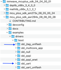
    Ans:Use this SBL_UART application (available within mmWave MCU Plus SDK), follow the readme instructions
    You can even refer the SBL_JTAG_UNIFLASH to flash the application.

    Refer this Appnote to understand more about different SBL modes https://www.ti.com/lit/pdf/swra760 

    Q6) Why DSS core is not connected after I flash SBL and main application to AWR294x EVM?

    Ans:When device is powered up, DSS and BSS cores are by default in the halted state. With MCU+SDK, SBL takes responsibility to bring these cores out of reset, load firmware/application image content to corresponding RAMs and then finally unhalt these cores.

    So make sure that you have flashed SBL and main-application (containing MSS, BSS and DSS images contents in right format) in SOP5 (UART boot) mode, then boot the device in the SOP4 (QSPI Functional) mode.

    Even with this, you are not able to connect to DSS core via CCS (JTAG), then check these register while connecting from R5F/MSS core from CCS

    Register address Expected Value Description
    0x02120804 0x00000707

    ROM Eclipsed to RAM for user app image by the RBL (ROM Bootloader)

    MSS_CTRL:R5_ROM_ECLIPSE

    0x05200020

    0x018F0028

    BSS Unhalted by the SBL

    RSS_PROC_CTRL:RSS_CR4

    0x05020400

    0x70000111

    BSS FW Development mode for AWR294x ES1.0 only.

    RSS_CTRL:BSS_CONTROL

    0x06000020

    0x00000030

    DSS unhalted by the SBL

    DSS_RCM:DSP_PD_STATUS

    If you don't find the cause or clue with above suggestion then another possibility if DSS image content which is loaded by the SBL may be corrupted and DSS core might be executing on some random code flow. For this you may need to check if MetaImage file which you flashed contains the right DSS image.  Or readback the DSS image (DSS_L2: 0x8080 0000)  via CSS (connected over R5F core) and compare with your original binary DSS content.

    Q7) How to port MCU+ QSPI driver to my custom sFlash part?

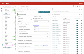
    Ans: Refer mmWave SDK User guide document (section 'How to use custom flash device')

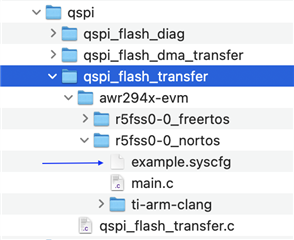
    Use the syscfg tool provided along with the SDK and configure the custom flash part there. For basic understanding first refer QSPI driver 

    SysConfig Tool is available /mmwave_mcuplus_sdk_04_04_00_01/sysconfig_1.14.0 (sysconfig_gui.bat)

    /mmwave_mcuplus_sdk_04_04_00_01/mcu_plus_sdk_awr294x_08_06_00_28/examples/drivers/qspi 

    Based on this understanding, you can do similar change for your application sysConfig file to support custom sFlash part.

    Set build environment in the command line (follow instruction in SDK user guide pdf: 'Setup the Build Environment') then switch to below path to open the SysConfig GUI for given example application

    C:\ti\mmwave_mcuplus_sdk_04_04_00_01\mcu_plus_sdk_awr294x_08_06_00_28>gmake -s -C examples/drivers/qspi/qspi_flash_dma_transfer/awr294x-evm/r5fss0-0_nortos/ti-arm-clang syscfg-gui

    Select Flash option here and set required parameter as per your custom sFlash part.

    Q8) How 1D-FFT chirp processing is triggered in AWR2944?

    Ans: There is the function DPM_init_DeviceHook in the file C:\ti\mmwave_mcuplus_sdk_04_03_00_01\mmwave_mcuplus_sdk_04_03_00_01\ti\control\dpm\platform\dpm_awr294x.c, which enables frame start and chirp available interrupts. So once the data is available in ADC buffer and ADC_CAPTURE_COMPLETE is set an ISR is raised, which enables the channel EDMA_DSS_TPCC_A_EVT_RSS_ADC_CAPTURE_COMPLETE to transfer data from ADC buffer to HWA memory.

    EDMA channel of EDMA_DSS_TPCC_A_EVT_RSS_ADC_CAPTURE_COMPLETE is triggered by the chirp available interrupt which transfers data from ADC buffer to HWA memory.

    Q9) AM2732+AWR2243 OOB demo trigger for ADC raw data

    Ans: In AM2732+AWR2243 demo, we get the ADC data into HWA using memory CSI2 interrupt from AWR2243 or via LVDS streaming mode. Therefore, no EDMA is required to bring in ADC data to HWA memory. Refer to CSI2 reference in TRM to get a better understanding of it. If LVDS streaming is not enabled, the M0 and M1 of HWA is set as ping pong buffer of CSIA RX, and thus EDMA is not required, and the device will maintain and refresh ping pong buffer.

    Q10) Where is CCS project for OOB demo?

    Ans: Visit this link for CCS project for all mmwave sensor device variant OOB demo CCS project https://dev.ti.com/tirex/explore/node?node=A__ADFsv62CVEotGtkwF2Zxlg__radar_toolbox__1AslXXD__LATEST

    Q11) How to launch DSS via programmatic API?

    Ans: refer this e2e (2) MCU-PLUS-SDK-AM273X: AM273X - Arm-based microcontrollers forum - Arm-based microcontrollers - TI E2E support forums . Need to check with team if sequence is required.

    Q12) AWR2944 Sampling Temp and Voltage in different frames

    Ans:  Yes, we can measure both sample temperature and sample voltage. One of the ways is to take the C:\ti\mmwave_mcuplus_sdk_04_03_00_01\mcu_plus_sdk_awr294x_08_04_00_01\examples\drivers\gpadc\gpadc_group_channel_read\gpadc_group_channel_read.c example and add APIs for temperature reads from C:\ti\mmwave_mcuplus_sdk_04_02_00_02\mcu_plus_sdk_awr294x_08_04_00_01\examples\drivers\gpadc\gpadc_temperature_sensor_read\gpadc_temperature_sensor_read.c.

    Q13) MCAN bit-rate calculation (mCAL):

    Ans:   (+) AWR2944: MCAN bit rate calculation - Sensors forum - Sensors - TI E2E support forums

    MCAN bit-rate calculation (SDK): C:\ti\mmwave_mcuplus_sdk_04_03_00_01\mcu_plus_sdk_awr294x_08_04_00_01\source\drivers\mcan\v0\mcan.c

    Q14) Is Fallback images supported in the AWR294X SBL?

    Ans: RBL (ROM Bootloader) by default reads from 0th offset of sFlash looking for valid SBL image, in case of failure it falls back to next offset set to 512KB (0x40000). Please refer to the following thread: (16) AWR2944: Whether Fallback images is supported? - Sensors forum - Sensors - TI E2E support forums

    Q15) What is the relation between mmWave API and mmWave Link. Does mmWave API contain all the function of mmWaveLink ?

    Ans: The mmWaveLink provides low level API's to control, configure and monitor the RF sub system. mmWave API's is a more abstracted version of mmWave Link which is more convenient and easier to use for users. It in turn uses all the API's from mmWave Link. If your application requires more control/ you want to use more complex features of the RF subsystem then you can use the Link API's. It will depend on your application requirement.

    Q16) How can we change the start frequency (any other variable parameter) of the chirp signal for every individual chirp? What are the possible techniques to achieve this?

    Ans: The Chirps can be configured in a number of ways.

    1) Legacy Chirp Configuration: For this you will have to make the API call to ChirpConfig for as many number of times as the number of chirps you want. If you want to configure all 512 chirps then it will be those many calls to set the CHIRP_FREQ_START_VAR to your desired values.

    2) Advance Chirp Configuration: In advance configuration you can either program a LUT dither value or a delta dither value one time and apply to your chirps thus easing out the process for you. For all the required documentation on this please refer to the DFP user guide. For your use case programming the delta dither will be the ideal solution. Please find the link below for DFP (mmWave Device Firmware Package)

    MMWAVE-DFP Firmware | TI.com

    3) Dynamic Chirp Configuration: You can dynamically apply changes to your chirp while the frames are ongoing by calling the appropriate set of APIs’. This is also documented in the DFP user guide (section on dynamic chirps).

    Refer ---mmWave DFP for more RF-Front-end or DFP related queries

    Q17) What are the flash variants supported by the mmWave radar sensors?

    Ans: The app note documents all the flash variants supported by the mmWave radar sensors.

    IWR6x43 Flash Variants Supported by the mmWave Sensor (Rev. D) (ti.com)

    Q18) For AWR2944 device what are the implementation changes to include the 4th Tx in gain mismatch and phase mismatch offset values?

    Ans: Two new API’s have been included in the DFP package (from 2.4.x.x). The AdvTxGainTempLutGet and the AdvTxGainTempLutSet API’s are added and should be called 4 times with the Tx_Profile and the Tx_Channel to cover all the 4 transmitters.

    Q19) How to get on chip temperature readings for mmWave devices?

    Ans: AWR294x device contains two instance of GPADC to read the device temperature (mmwave_mcuplus_sdk_04_04_00_01/mcu_plus_sdk_awr294x_08_06_00_28/source/drivers/gpadc: GPADC_readTemperature), one if with MSS where application can read digital (DSP, HSM, HWA) temperature, another is with BSS where you can read temperature of Rx/Tx block of rf-front end.

    There are two provisions for Rf-front end temperature:

    RF_TEMPRATURE_GET_SB: This sub block provides the device temperature sensor information. It’s a straightforward API to the sensor info. mmWaveLInk  rlRfGetTemperatureReport API for this SBID.

    MONITOR_TEMPRATURE_REPORT_AE_SB: This API is a Monitoring Report API which the mmWave device sends to the host, containing the measured temperature near various RF analog and digital modules. The AWR device sends this to host at the programmed periodicity or when failure occurs, as programmed by the configuration API SB. This report will also provide status flags for threshold checks under this monitor.  rlRfTempMonConfig mmWaveLink API.

    Q20) How to reduce power consumption for TI mmWave radar sensors

    Ans: To reduce the power consumption, you can try the below

    1. Power is mostly consumed by the device in Active chirping mode. So basically, if you reduce the chirp duty cycle (ratio of active framing and total frame period), that will help in ultimately reducing the average device power. This can be done either by decreasing the frame active time (keeping total frame time constant) or by increasing the inter-frame idle time.
    2. You can also disable the active number of transmitters at once to reduce power (or reduce the output power/transmitting power of TX)
    3. You can save power by configuring Interchirp Idle time > 10us. In that case, most of the blocks in the device are turned off in the interchirp idle time to save power.
    4. You can use Low power ADC mode (half rate ADC mode), but this puts a limitation on the usable IF bandwidth. Please refer to the mmWave Interface Control document for that.
    5. Using a real only complex chain can also help here.

    So, it's basically weighing various factors now. Obviously, each of them comes with a cost and have their own pros and cons, but these are some of the ways in which power can be optimized.

    Q21) What is the maximum number of samples that can be captured?

    Ans: The valid range is from 2 to maximum allowed samples. The maximum is determined by all the enabled RX channels’ data fits into 16 kB memory in AWR1243/xWR1443/AWR2243/xWR6243/AWR294x or 32 kB memory in xWR1642/xWR6x43/xWR1843, with each sample consuming 2 bytes for real ADC output case and 4 bytes for complex 1x and complex 2x ADC output cases.

    Q22) How to extract the IIB info from the interference localization block?

    Ans: Not possible. You can only have a total count of how many samples were corrupted.

    Q23) Questions related to the source code / algorithms of the Visualizer

    Ans: Use F12 when the demo visualizer is open in the browser and view .js source code (refer mmwave.js)

    Q24) How to perform scalar / vector multiplication using HWA?

    Ans: Refer the CMULT modes 0101b for scalar product, 0110b & 0111b for vector multiplication in the pre-processing block of the FFT engine (Sec 28.7.6 of the TRM).

    Q25) How to determine chirp time when 1D is done with HWA?

    Ans: Assuming you are planning to use HWA for your chain, the time interval between chirps needs to be adjusted based on how long your rangeProcDDMA takes per chirp (As preprocessing + 1D FFT + compression is done chirp wise and then copied to L3).

    Initial latency takes around less than 100 cycles depending on preprocessing blocks available (worst case), FFT Cycles = roughly [N + (N * BCNT)] cycles (where N = FFT Size). [FFT block]

    Compression block takes about ACNT+ (ACNT* N) number of cycles.

    You can also add around 100 cycles for EDMA trigger latencies.

    Total number of cycles/ Clock speed of HWA (300 MHz) should give you chirp processing time. So, make sure your chirps have sufficient time according to this thumb rule.

    Q26) Is it possible to copy from same source with different TPCC to different destination address triggered by the same event?

    Ans: Yes, it is possible, but the data transfer rate will be approximately halved.

    Q27) Relative power of RX in mW or dBm

    Ans: The fullscale power of Rx ADC based on the type of sampling available is 20mW or 13dBm. You would have to scale your relative power accordingly from the range profile.

    Q28) Why use DBSCAN over other clustering algos like K-means in our demos?

    Ans: DBSCAN was found to be a good algorithm for finding clusters in radar point cloud and hence was chosen for use the same in our demos. It finds clusters of varying shapes (depending on the nature of point cloud spread which is subject to change with each new observation) based on the density of points across different subsections of the point cloud spread (two main parameters that define the density are Epsilon and the number of points). It performs really well on a noisy radar point cloud by clustering points within higher density regions and ignores the sparser sections which resemble. DBSCAN can address the issue of irregular shaped clusters much better than K-means. Furthermore, K-means clustering will classify all points (including noise points and other points of no interest) on your dataset into their respective clusters. 

    Q29) How the RTI counter value is calculated and fed into the register?

    Ans: Please refer the following thread: AWR2944: AWR2943 - Sensors forum - Sensors - TI E2E support forums

    Q30) Within the c6000 compiler, are there options which would disable the compilation against the standard header files for C / C++ objects. Like e.g nostdlib, nostdinc.

    Ans: There is no direct option such as nostdlib but there can be a workaround using the following linker options:

    With this you should be able to override which libraries to link over the standard library/default search paths.

    Q31) What are the different types of resets?

    Ans: There are 3 types of resets: warm reset, power on reset and soft reset.
    So, the power on reset will reset the complete device and will start the execution again from the RBL and then the SBL.
    Warm reset is similar to power on reset but you it retains some of the registers value.
    A soft reset is only for the individual core and the MSS and the DSS can be soft reset and the other cores will not be reset.
    To reset the R4f BSS core you can only perform the power on reset or the warm reset, soft reset is not possible.

    Q32) How to enable the DMA in the SBL_QSPI?

    Ans: So, there is an issue with the 4.2.0.3 SDK (incorrect header), you can follow the below steps for enabling DMA (install the 4.2.0.2 SDK first):
    1)Copy the APP generate scripts from SDK4.2.0.2 to SDK4.2.0.3. To combine the XE66 and XER5F to a single BIN
    2) Script is mentioned below that you need to perform in order:
    call C:\ti\mmwave_mcuplus_sdk_04_02_00_02\mmwave_mcuplus_sdk_04_02_00_02\scripts\windows\setenv.bat
    call C:\ti\mmwave_mcuplus_sdk_04_02_00_02\mmwave_mcuplus_sdk_04_02_00_02\scripts\windows\checkenv.bat
    call %MMWAVE_SDK_INSTALL_PATH%/scripts/windows/generateMetaImage.bat app_sdk4203_DDM.appimage awr2944
    _mmw_demo_mssDDM.xer5f %AWR294X_RADARSS_IMAGE_BIN% awr2944_mmw_demo_dssDDM.xe66
    call %MMWAVE_SDK_INSTALL_PATH%/scripts/windows/generateMetaImage.bat app_sdk4203_TDM.appimage awr2944
    _mmw_demo_mssTDM.xer5f %AWR294X_RADARSS_IMAGE_BIN% awr2944_mmw_demo_dssTDM.xe66
    3)This BIN can be load and run by SBL enable DMA.

    Q33) Even if I am setting the right clock settings, the clock value is not being reflected in the registers/output (Lauterbach)?

    Ans: We found out that Clock settings from the SBL was being overwritten in the evaluation board Trace32 (Lauterbach) init scripts and hence there was different SYS_CLK and a different input clock frequency for the peripherals

    Q34) How to receive data from CSI2 data?

    Ans: Please follow the steps in the link: (+) AWR2944: receive data from CSI2 - Sensors forum - Sensors - TI E2E support forums

    Q35) How does DMM interrupt work, does it require modification in callbacks?

    Ans: So, the events are already mapped in the TRM, you will just have to write the trace mode packet of the DMM to which particular bit you want to enable and then stream is over the CSI2.
    Even if you connect the interrupt with the DMM, it's not like the interrupt behavior will change, it is just driven from the DMM. So, the customer does not need to change the callback function register.
    Refer the link: (+) AWR2944: Question aobut AWR2944 HIL - Sensors - INTERNAL forum - Sensors - INTERNAL - TI E2E support forums

    Q36) Pwm_SetPeriodAndDuty function has an issue when we set 100%Duty Cycle and change to a lower one (between 50%-100%) the voltage signal is stuck to 100% DutyCycle.?

    Ans: This is not a bug, this is the expected behavior as you are supposed to set it to idle before changing the period or duty cycle. 
    Before you change the duty cycle, you call the Pwm_SetOutputToIdle() api and then set the duty cycle.

    Q37) Does the AWR2944 support the nested interrupt as well and how many levels of nested interrupts?

    Ans Yes, it is supported and the number is 16.

    Q38) Where are the files related to PHY configuration for Ethernet in mcu plus sdk and how to support for other PHY's?

    Ans: The PHY related functions are available in the C files in the location 'mcu_plus_sdk_awr294x_xxxx\source\networking\enet\core\src\phy'. Refer to the existing implementation of dp83867 PHY to create your own support for other PHY's.

    Q39) Do you have a basic example in mcu plus sdk to test the functionalities of Ethernet in AWR2944?

    Ans: Refer to the example in 'mcu_plus_sdk_awr294x_xxxx\examples\networking\enet_tx_scatter_gather'. This example makes use of only the drivers without any dependencies on LWIP stack.

    Q40) Can the Ethernet descriptors be placed anywhere in the memory?

    Ans: The Ethernet descriptors are recommended to be placed in non-cached memory; else additional cache write back operations may need to be done inside the ethernet driver.

    Q41) How to enable/disable cache for a specific region/memory area for R5F core?

    Ans: This can be done by defining a region in ARM MPU in R5F core and setting it to either cached or non-cached region.
    In mcu plus sdk this can be configured in sys-config.
    Refer to ARM documentation for more info on ARM MPU.

    Q42) What are the addresses in SDF that RBL can load the SBL from, in QSPI boot mode and is it configurable?

    Ans: The RBL first searchs for a valid image at 0x0 of SDF. If this fails, it tries to find a valid image at offset 0x40000 in SDF memory. This cannot be changed or configured.

    Q43) What are the types/variants of devices available in AWR2944?

    Ans: Three variants are available, General purpose, Development secure and secure. Refer to device datasheet for details.

    Information General: