This thread has been locked.

If you have a related question, please click the "Ask a related question" button in the top right corner. The newly created question will be automatically linked to this question.

LDC1101: LDC1101

Part Number: LDC1101

Hi!

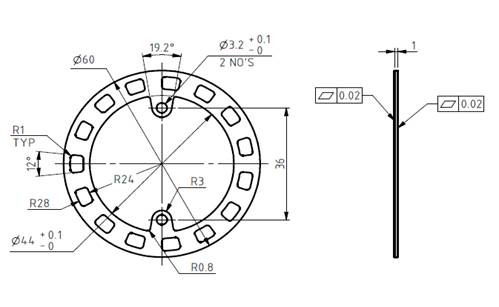
I have designed the coil as the size of d_out is 55.5mm and d_in is 49mm. I have used only one layer .

Following spec

1) Coil_ outer Diameter is 55.5mm

2) Coil _inner Dia is 49mm

3) No of Turns - 4 Nos

4) Layer - 1

5) Spacing between Traces - 0.8mm

6) Coil Width - 0.2mm

Now I am operating the clock frequency as of 16MHZ.

If I touch on the sense, inductance are getting affected but with the metal  not much change.

what would be the issue ? Cant we check without SPI this sensor Inductance?

what is the registers used in LDC1101

Register Addr Value
RP_SET 0x01 0x45
TC1 0x02 0xDE
TC2 0x03 0xFD
DIG_CONG 0x04 0xE7
LHR_RCOUNT_LSB 0x30 0x00
LHR_RCOUNT_MSB 0x31 0x02
LHR_CONFIG 0x34 0x01


  • Hi Muthu,

    If you are touching the coil with your hand, you are seeing a capacitive response, not an inductive response. You can read more about that effect here: https://e2e.ti.com/support/sensors/f/1023/t/295036#Q18

    I have a few questions about your setup that will help me debug your issue:

    1. What is the size of your target? What is the material? How close is the target to the coil?
    2. How have you connected your coil to your LDC1101? Typically coils need a minimum of two layers in order to route both ends of the coil to the LDC1101. Are you using wires?
    3. Are you using L-only mode or RP+L mode?
    4. What capacitor are you using with your coil? Have you measured the Rp value of your coil? If not, I recommend this application note: http://www.ti.com/lit/an/snoa936/snoa936.pdf . The Rp value needs to be within the range specified in the electrical characteristic table of the datasheet in order for the LDC1101 to drive the coil

    Best Regards,

  • Hi!
     
    I hope you can see the coils from the below snapshot Fig 2. I have chosen the circular coil and it is one layer. We don’t need to have high inductance in our application since the coil diameter is larger one.
     
    1.     What is the size of your target? What is the material? How close is the target to the coil? – I also have attached the target wheel image in this Fig1. Dia-60mm ; Thickness-1mm. Material- Mild Steel.
    2.     How have you connected your coil to your LDC1101? Typically coils need a minimum of two layers in order to route both ends of the coil to the LDC1101. Are you using wires? Yes. I am using LDC1101 but I have used only one layer which is 4 no of Turns. I have attached those image as well in this. One Layer – 4 Turns
    3.     Are you using L-only mode or RP+L mode? – I am using L-only Mode
    4.     What capacitor are you using with your coil? Have you measured the Rp value of your coil? If not, I recommend this application note: http://www.ti.com/lit/an/snoa936/snoa936.pdf . The Rp value needs to be within the range specified in the electrical characteristic table of the datasheet in order for the LDC1101 to drive the coil – Capacitor -330pf I haven’t measured Rp Value so far. Just I am stimulating that what would be the inductance value as per my coil design.
                                          Fig 1:   Target


                                    Fig 2: Inductive Sensor
     
    Regards,
    Muthukumar M | Aditya Auto | R&D | 91-8600035302.


  •  
    Hi!
     
    Further to the below continuation,
     
    I have extracted this output parameters as based on my coil design.


  • Hello Muthu,

    My apologies for the delayed reply. Can you clarify if the boxes in your target are cutouts? This would make the target much more difficult for the LDC to detect. The target should be smooth without gaps or cutouts, which disturb the path of the eddy currents that flow on the surface. In addition, if your target is too far from the sensor then the LDC will have trouble detecting it. For an ideal target (no gaps, highly conductive, and at least as large as the coil), the maximum sensing distance of the LDC1101 is ~100% of the sensor's outer diameter.

    Best Regards,

  • Hi!

    Thanks for your feed back.I have made one spiral coil with the same diameter  at externally with same dia of 53mm (Coil made manually with 28gauge wire) and found ok with desired result .

    But I have another doubts on your  interface data.

    I am using four registers in my coding.

    There are Rp Set Value,TC1 Value ,TC2 Value and Dig Config Value. Apart from this anything to consider for calculation?

    Query No:1

    I am getting the result only when Rp Set Value is 0x67. if i change this value into 0x45 or some other value ,Result  is getting zero. Why?

    Query No:2

    How to set Nominal current in  register(CHx_IDRIVE Register Field Value)? 

    I am using one register rxbuffer[4] that is giving the result.Please clarify

  • Hi Muthu,

    Actually, if you would like to use LHR mode then you do not need to configure several of the registers you listed. I suggest disabling Rp measurements if you'd like to use LHR mode. There are instructions for this in section 9.1.11 of the datasheet. All of the registers you need to configure for LHR mode are listed in sections 9.1.9 through 9.1.11 of the datasheet. You may also wish to customize the LHR_STATUS register (0x3B).

    1. For LHR mode, you need to set this value according to these instructions: http://www.ti.com/lit/an/snoa950/snoa950.pdf

    2. Are you talking about the RP_MIN register field, which configures the drive current for LHR mode? If so, follow the instructions in the app note above. 

    Best Regards,