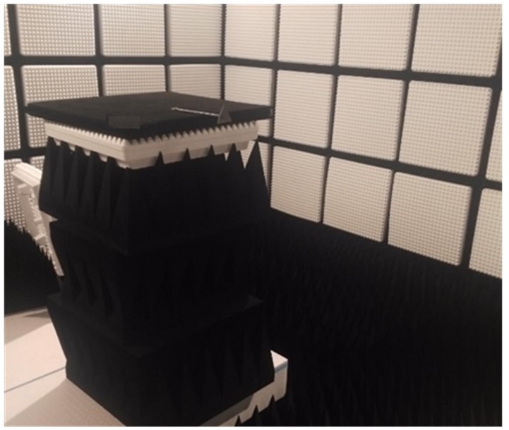
Can you advise the best setup for calibration. I have designed a product using the IWR6843 module and am now working through quality checks and was wondering what the best setup for calibration is.
I have been using the calibration procedure outlined in the documentation (as I understand it) but I'm seeing some very large calibration values which I need to get to the bottom of. I am not sure if this because of a manufacturing tolerance issue or if my calibration setup is the problem, or if this normal. I will also need to build a test rig for the manufacturer in due course so need something that will work in a factory setting. I am using the reference design for the IWR6843ISK antenna.
For testing, I have a 1200mmx1200mm sheet of metal which is placed 1.000m away from the sensor and I then run the calibration routine as explained in the documentation. I have also found the results to be sensitive to the exact setup (moving things a few mm can make a noticeable difference).
Typical calibration results:
Range bias:0.08221510052680969,
Phase bias real 1:-0.6945499777793884, Phase bias complex 1:-0.01834000088274479,
Phase bias real 2:-0.4772599935531616, Phase bias complex 2:-0.6360200047492981,
Phase bias real 3:-0.6244800090789795, Phase bias complex 3:-0.5064399838447571,
Phase bias real 4:-0.12756000459194183, Phase bias complex 4:-0.6656500101089478,
Phase bias real 5:-0.7667499780654907, Phase bias complex 5:-0.23654000461101532,
Phase bias real 6:-0.32686999440193176, Phase bias complex 6:-0.8762199878692627,
Phase bias real 7:-0.5512099862098694, Phase bias complex 7:-0.76569002866745,
Phase bias real 8:0.059450000524520874, Phase bias complex 8:-0.7704799771308899,
Phase bias real 9:-0.8706099987030029, Phase bias complex 9:-0.021940000355243683,
Phase bias real 10:-0.5823400020599365, Phase bias complex 10:-0.7919600009918213,
Phase bias real 11:-0.7581800222396851, Phase bias complex 11:-0.6520699858665466,
Phase bias real 12:-0.12848000228405, Phase bias complex 12:-0.8274800181388855
Questions:
1. What does the ideal calibration 'test rig' look like?
2. If I were to write a testing specification for the manufacturer, what would sensible tolerances be?
3. What could be causing such large phase bias values and should I be concerned?
-
Ask a related question
What is a related question?A related question is a question created from another question. When the related question is created, it will be automatically linked to the original question.


