This thread has been locked.

If you have a related question, please click the "Ask a related question" button in the top right corner. The newly created question will be automatically linked to this question.

TS3A27518E-Q1: Output resistance in the off state

Part Number: TS3A27518E-Q1
Other Parts Discussed in Thread: TS3A27518E

Hi Team,


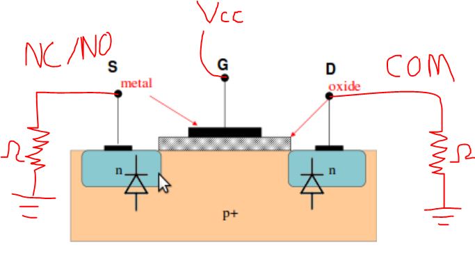
My customer has asked us for the output resistance for the NC and NO pins when they are turned off. I did see that isolation graph on the datasheet, but do we have an approximate value for the output resistance in the off state?


Regards, Diego

  • Diego,

    The off state resistance for a passive FET switch can be calculated by the off leakage current specs in the datasheet for a DC signal.  You can use the max voltage placed on the signal path divided by the current through the switch to get the resistance of the signal path in the off state. 

    This post has an example calculation of the off resistance.

    For AC signal you need to look at the off isolation since the signal path will impedance will be lower at higher frequencies.

    Thank you,

    Adam

  • Thank you for the support Adam.

    Is there a maximum trace length defined for this device on the data lines?

    My customer plans on having it connect to a separate board, and is worried about the trace lengths.

    Regards, Diego
  • Diego,

    These types of signal switches are passive FET switches and do not have any drive capability sourcing or sinking current.  The trace length calculations will need to based on your transmitter strength and your receiver sensitivity.  

    There is more information on how these pass FETs work in this e2e thread

    This application note is also useful in the basics of passive FET switches.

    Do you know what parts are driving and receiving the data?  What protocol are they using?  

    Thank you,

    Adam

  • Thank you for the last link and information Adam.

    My customer wants to know what is the smallest resistor they can use as a pull down to ground on the NC/NO pins when using 1.8V logic. 

    They want to have a 50Ohm termination in one of the outputs, and want to make sure this won't be an issue. 
    Regards, Diego

    You once recommend  to pull down signal with 10k in case they are grounded.
    What smallest resistor would you use for 1.8V voltage level in order to maintain functionality?
    Reason I’m asking we may need  a 50Ohm termination to ground. 
  • Diego,

    The NC/NO pins are the drain or source of a mosfet and placing a pull down of any size will not make any difference in just this circuit.

    The pull down resistor on the signal path COM, NC, or NO will likely effect the other components in your system.  Do you have a diagram with the other components in your system?  What is the circuit driving the switch ( push pull, open drain, etc.)?

    Thank you,

    Adam

  • Hi Adam,

    Thank you for the confirmation.

    Another engineer using the same part wanted to know how should they handle the device during power on in order to keep the I/Os in high impedance.

    Would a pull up from the EN to the VCC pin be sufficient?

    Regards, Diego

  • Diego,

    The TS3A27518E has the powered off protection feature and will be Hi-Z when Vcc = 0 V.  

    TI recommends adding pull up or pull down resistors on the digital logic pins to prevent undesired conditions during power up.  If you would like to remain Hi-Z during power up you should place the resistor to Vcc.

    Thank you,

    Adam