This thread has been locked.

If you have a related question, please click the "Ask a related question" button in the top right corner. The newly created question will be automatically linked to this question.

MUX508: The break-before-make delay is too long to be accepted by customer

Part Number: MUX508

Hi BU Experts,

My customer is using MUX508. 

They found an issue about the break-before-make delay.

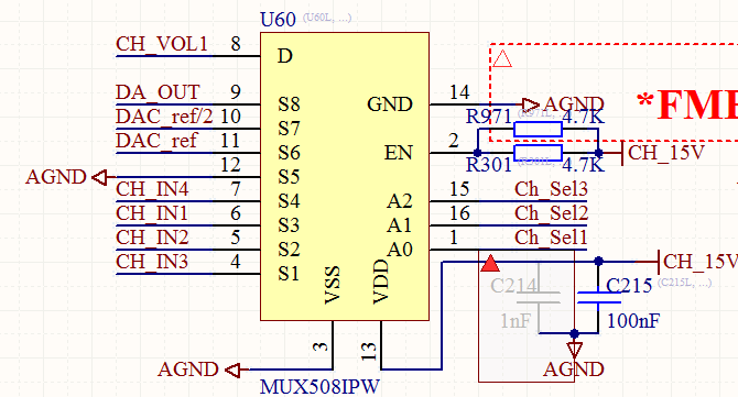
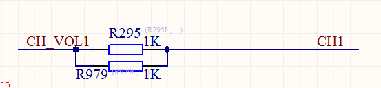
Below is the SCH. VDD=15V, S3=15V, S4=0.76V.

when the S3 is switched to S4 (A0 from 0 to 1), there will be ~120us delay in which the output (S8) will drop to 0.6V first, and then rise to 1V, and go back to target 0.76V finally. You can refer to the waveform attached (CH1: OUTPUT S8, CH2:A0).

When the input S3 voltage is lower, the delay can be shorter. 

I can't find the break-before-make delay data when input is close to VDD.

Customer can't accept so long delay.

Could you let me know the reason and what actions can do to improve it?

  • Hi Zhengxing,

    From the waveform you captured, this is a settling time issue.

    It will be very helpful If you can draw a circuitry and let us know how your customer generates 0.76V. I assume 0.76V is not from an ideal voltage source. 0.76V seems to be from a voltage source with high resistance.

    Also for the same reason, it will be clearer for me if you can draw the output side circuitry, the circuitry attached to Pin 8. I would like to see how much capacitance attached to that pin.
  • Hi Fan,

    Thanks for reply. Happy Chinese New Year!

    1. Please check the circuits as below.

    1) the CH_IN1, CH_IN2, CH_IN3, CH_IN4 circuits are the same. So the voltage source resistance is not an issue.

    2) Pin8 is connected to ADC's input through the resistors R295 and R979. No capacitor over there.

    2. Customer did an experiment. When exchange the ICs across different boards, for certain IC, it will show the same settling time on different boards.

    For above two, it seems it is not relevant to external circuit, but the IC ifself.

    Could you please help analysis it and give your suggestions? thanks.

  • Hi Zhengxing,

    Thansks for sharing this schematic. It's great for me understand the signal flow.

    You already shared the scopeshot of A0 and D. Would you capture A0, D, S3 and S4 altogether? I would like to see the settling effect of MAX44248 because this opamp is going to determine how fast the D settles to 0.76V.
  • Zhengxing,

    We haven't seen a response from you in a while . Have you resolved this issue? We are going to close this issue but you may reply to reopen the case.

    Thank you,
    Adam