This thread has been locked.

If you have a related question, please click the "Ask a related question" button in the top right corner. The newly created question will be automatically linked to this question.

SN74CBTLV3245A: 25M or 50M data rate system. When do the signal integrity simulation, whether they can use the on resistor 5ohm here?

Part Number: SN74CBTLV3245A
Other Parts Discussed in Thread: SN74CBTLV3257, TMUX1511

Hi team,

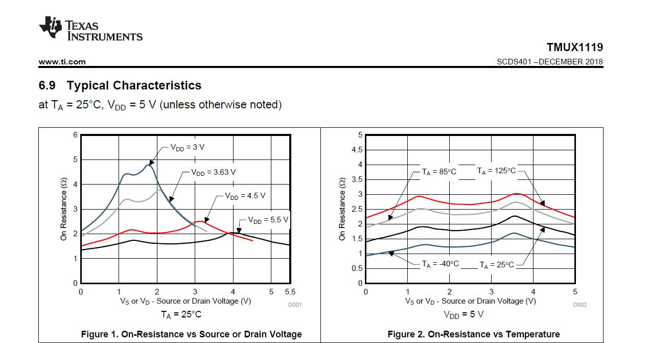
My customer wants to use the device in the 25M or 50M data rate system. When do the signal integrity simulation, whether they can use the on resistor 5ohm here?

In my opinion, it cannot, because the parallel cap will have smaller resistor than the Rdson 5ohm.

So which value we need to use in the simulation, or do we have the SI simulation module?

Thanks. 

  • Frank,

    You can add a series resistance and parallel capacitance to model the switch.  The on and off state capacitance values in the datasheet are measured at the pin and basically lump all the capacitances below together. 


    This is a graph comparing a through path to a path with the SN74CBTLV3257 device with a 75MHz clock.  You can see there is a slight change in the rounding edge but not much of an issue.  This will be similar performance to the SN74CBTLVXXXX family.

    Thank you,

    Adam

  • Hi Adam,

    The datasheet only has the value of Ci and Co, do we have other data?

    BTW: For the Ron, which value we can select? The VCC is 3.3v. Vin is about 3.3v.

    Thanks.

  • Frank,

    The SN74CBTLV3245 device is an older part and doesn't have more data than is stated in the datasheet.

    For the capacitance value use Cio since Ci is the capacitance of the control logic pin and not the I/O signal path.    

    For Ron you can be safe and use the worst case value 15 ohm but it should be less than that when the voltage on the input is near the supply rail or ground for this transmission gate switch. 

    Below is an example of a transmission gate type switch and the Ron response across input voltage where you can see the higher Ron is when the input voltage is in between the IC supply rail.

    What are you connecting to the device?  If you are using a low current data transmission application 10mA across 10 ohm Ron of the switch is only going to have a voltage drop of 100mV which shouldn't be anywhere close to the Vih of the receiver.    

    If you would like a device with more detail and s-parameter and IBIS models you can look at the new TMUX1511 device.

    Thank you,

    Adam