This thread has been locked.

If you have a related question, please click the "Ask a related question" button in the top right corner. The newly created question will be automatically linked to this question.

TMUX1108: compared with SN74CB3Q3251, which is better for a 400Mhz equivalent pulse

Part Number: SN74CB3Q3251
Other Parts Discussed in Thread: TMUX1108, , SN74CBT3251

hello team

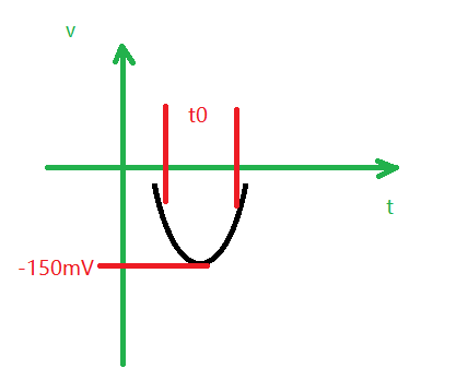
I should choose a 8:1 mux to select each sensor pulse output, the worst case sensor output is roughly like below; half height width t0=1.1ns; equivalent to 400Mhz cycle wave;

Question 1: Currently I use TMUX1108, BW is 90M, but when I test my worst case wave, I did not see much attenuation as calculated Vo=0.2*Vin; But when I using network analyzer test S21, there is -14dB around 400M, why they are different; Can you share the s-parameter of 1108?

Question 2: is SN74CB3Q3251 a better choice for my application? because its BW is 500M, and Ron and Con are smaller.  But as I know from one thread about SN74CB3Q3251, its insertion loss is about -3dB @200M; would this be a bad point for me.

Qunstion 3: how about the charge injection parameter about SN74CB3Q3251?

Many thanks!

https://e2e.ti.com/support/switches-multiplexers/f/388/p/733028/2707226?tisearch=e2e-sitesearch&keymatch=sn74cb3q3251#2707226

  • Hi User6041007,

    Using a multiplexer for selecting different sensors is a very common application for the TMUX1108.

    Question 1: The Bandwidth of the TMUX1108 as you mentioned is 90MHz and is measured on a network analyzer, this is why you can see up to 14dB of attenuation at 400MHz. Can you further explain your equation where you are not seeing attenuation of the signal at 400Mhz? We do not currently have an S-parameter model for the TMUX1108. You mentioned not seeing much attenuation with your worst case wave, is this measured on a lab setup?

    Question 2: The SN74CB3Q3251 device has a BW of 500MHz as you mentioned. The thread you are referring to with -3dB at 200MHz is actually for the SN74CBT3251. The "CB3Q" device have a higher bandwidth. However, these devices are specified for single supply applications and it looks like you signal is a negative voltage which is outside of the recommended operating conditions.

    Question 3: We do not have any parameter data on the SN74CB3Q3251 charge injection paramater - if you are looking to optimize for this spec I would recommend staying with the TMUX1108.

  • Question 1: it is measured on my sensor sampling setup, and 400Mhz is from the real test waveform like shown before; The input voltage is about -150mV max and output of 1108 is about -120mV max. I want to do system simulation using S parameter, do you have a plan for providing this?

    Question 2: Currently , I supply TMUX1108 with 3.3V, so I think input voltage range is same with  SN74CB3Q3251; is that right? I want a >4:1 MUX with supply voltage down to 3.3, and BW can reach 500M

  • Hi User,

    To stay within the recommended operating conditions of the devices it is recommended to supply the TMUX1108 with dual supply voltages to allow a negative signal at the input. For example you can do 3.3V on VDD and -1V on VSS pins.

    Since these devices are lower bandwidths muxs there is not a current plan to add S-parameter data. How are you planning to use the S-parameter data to prove your circuit functionality?