A related question is a question created from another question. When the related question is created, it will be automatically linked to the original question.
If you have a related question, please click the "Ask a related question" button in the top right corner. The newly created question will be automatically linked to this question.
You can use two TS5MP646 cascaded for C-PHY application, However it depends on how sensitive your transmitter and receiver are in the signal path and the data rate or bandwidth your signal chain will need to support.
Also, each switch you place in serial will add these parasitic values to your signal path so you have to take them into consideration. See details at this e2e thread.
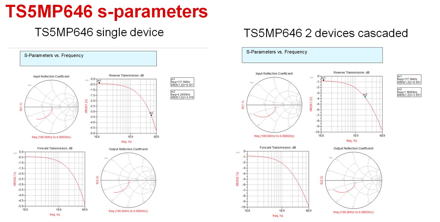
Having two TS5MP646 devices cascaded you have 2x the insertion loss (~-0.5 dB to ~1.0dB) and decreases bandwidth from ~4GHz to ~2GHz.
1. Our application is C-PHY v1.0 (2.5Gsps). Is there enough design margins for the insertion loss ~1dB and bandwidth ~2GHz of the two cascaded TS5MP646 devices in our application? i.e. is there enough margins to compensate for camera module FPC loss and PCB layout losses?
2. In "TS5MP645: What's the maximum datarate and video resolution supported?", TI Adam recommended the signal switch per channel bandwidth to be ~1.5 times the per channel data rate. i.e. 3 times clock rate, right? Is this the thumb of rule applicable to both of C-PHY and D-PHY? i.e. for C-PHY v1.0 (2.5Gsps) and D-PHY v1.2 (2.5Gbps), the recommended bandwidth is 1.25GHz * 3 =3.75GHz, right?
3. The simulation result you referred "TS5MP646: How many TS5MP646 can be used as serial? What happens when you cascade signal switches" is only applied for D-PHY or also for C-PHY? D-PHY signals are differential pairs and C-PHY signals are single ended.
4. In TS5MP646 datasheet, there is only measured insertion loss and bandwidth data. Can this data be applied for C-PHY? Or C-PHY is worse?
5. In TS5MP646 datasheet, minimum insertion loss is 0.65dB, typical differential bandwidth is 3GHz. Are these two data also applied for C-PHY?
6. In TS5MP646 datasheet, minimum insertion loss is 0.65dB, typical differential bandwidth is 3GHz. For our two cascaded TS5MP646 devices application, total insertion loss may be more than 1.3dB and total bandwidth may be less than 1.5GHz, right?
1: It depends on how sensitive your transmitter and receiver are in the signal path, what is the quality of the receiver As I mentioned earlier, having two TS5MP646 devices cascaded you have 2x the insertion loss (~-0.5 dB to ~1.0dB) and decreases bandwidth from ~4GHz to ~2GHz. (1.9 GHz in worst case)
2: Yes, It is recommended to select a switch with bandwidth that is 3x the signal frequency
No. 3, 4 and 5 apply to both C-PHY and D-PHY
6: Best way to check is by using the TS5MP646 S-Parameter Model with your application and see how much margin you get when you cascade 2 switches in series.
1. From TS5MP646 datasheet, minimum Differential Bandwidth is 2.7GHz. In best case scenario (without any losses), we will get a bandwidth of 1.35GHz for two cascaded TS5MP646, right? And this is worse than the one 1.9GHz you said.
2. How can I use the TS5MP646 S-Parameter Model with our application and see how much margin we get when we cascade 2 switches in series? Can you provide some documents and tools for me to reference?
1. The bandwidth decreases by Square root of 2, not by half when you add two parts in series. It will be around 1.9GHz if you are looking at min differential bandwidth of 2.7GHz.
I referred to 1.9GHz (worst case) when you are looking at typical bandwidth of 2.7GHz.
2. The s-parameter model for this part is in the general Sxy format. You should be able to open up the file and import the appropriate data values using Matlab, ADS, Cadence etc. There a presentation with port order when you unzip the downloaded model file from ti.com.
The usable bandwidth for 2 TS5MP646 cascaded. Refer to the s-parameter simulation, around 1.9GHz is the -3dB bandwidth. Note that this -3dB is lower than theoretical bandwidth as it includes the losses due to cross-talk, leakage etc.
With considering actual losses in system, we would recommend that the bandwidth should be at least 1.5 times per channel data rate.