This thread has been locked.

If you have a related question, please click the "Ask a related question" button in the top right corner. The newly created question will be automatically linked to this question.

TMUX1511: RMII 50MHz clock isolation using TMUX1511

Part Number: TMUX1511

Hi,

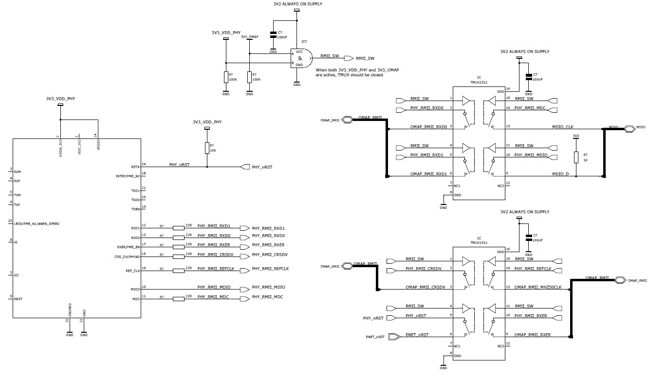
We are looking to use the TMUX1511 to isolate RMII signals between an Ethernet PHY and OMAP processor when the OMAP is not powered.  In this state we are awaiting a WoL magic packet.

As the 50MHz clock is active (along with other signals) during this state, we require a means to isolate it so as not power the OMAP via the 3.3V domain.

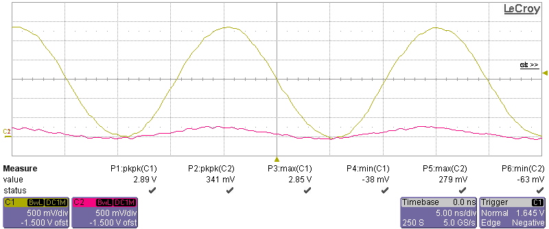
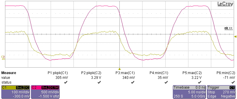
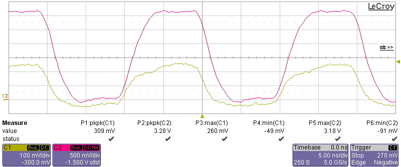
I have tested the TMUX1511PWR on the bench, and when the switch is disabled by grounding the SEL pin, and with a 50MHz clock fed into either the S or D pins, there is a 50MHz clock at ~450mV pk-pk on the other pin.

We are using 3.3V to power the TMUX1511 and the 50MHz clock is DC 3.3V fed from a function generator (Tr = 3.0ns)

From the datatsheet the off isolation @ 50MHz should be -30dB, but we are not seeing anywhere near that level

Can you advise as to the issue?

Thanks

Ian

  • Hi Ian,

    Placing the control logic pins at ground logic low will create a high impedance path between S and D. This doesn't automatically mean that D will go to ground unless you have pull down resistors on the COM side of the circuit.

    Can you post a Scope shot off the 50kHz signal on S and D?

    Thank you and best regards,

    Ambroise

  • Yellow = Input on S1

    Pink = Output on D1

    SEL1 = 0V

  • Hi Ian,

    does the same happen when you hook up a logic low voltage to SEL? (between 0V and 0.45V) 

    And how is the off isolation on the other pins? 

    Best regards,

    Ambroise

  • Hi Ambroise,

    Yes there is no difference when SEL is between 0V and 0.45V.

    The isolation between other pins is very good.

    Adding a 3k3 pull down resistor on the output D reduced the output swing to around 120mV whilst using a sig gen as the input.

    I tired this in-circuit with the actual 50MHz clock from the 10/100 Ethernet PHY going to the OMAP and the pull down resistor had no affect.  More-over in this real setup the output voltage swing is ~450mV

    Scope Trace: TMUX1511in off state in circuit inbetween PHY and OMAP

    Pink = input into S

    Yellow = output D

    SEL = 0V

    *Note different V/Div

    Scope Trace: TMUX1511 in off state in circuit inbetween PHY and OMAP

    Pink = input into S

    Yellow = output D (with 1k pull down)

    SEL = 0V

    *Note different V/Div

    Thanks

    Ian

  • Hi Ian,

    Just to be sure, did you try the 50MHz clock on other channels? 

    And could you share a partial schematic?

    Thank you,

    Ambroise

  • Hi Ambroise,

    Yes, I have tried on all channels and get the same result.

    We are at the stage of approving the IC before it makes it into our design, so I dont have a final schematic.  I have however quickly drawn a schematic of how we would be using the IC.  I have purposly left off siganls / components that are not relevant to this issue.

    Thanks

    Ian

  • Hi Ian,

    Is the Impedance on S & D known? the off isolation can be calculated as 10log10((Vout²/Rout) / (Vin²/Rin)) if the impedances are not the same.

    Can you check with your set-up?

    Thank you,

    Ambroise

  • Hi Ambroise,

    The input and output impedance should be matched between ~50-68 ohms.

    As mentioned the schematic provided is roughly how we would like to use the switch.  I am not trying to debug our circuit,  I have been trying to prove on the bench that the switch behaves as per the datasheet before we include it in a further design, and I can't see how it does.

    Are you able to supply a working test setup or better still provide scope traces of the switch isolating a 50MHz digital clock?

    Thanks

    Ian

  • Hi Ian,

    thank you for the details, I'll have to look into this in the lab, as we have not seen this behavior yet.

    Thank you for your patience,

    Ambroise

  • Hi Ian, we are expecting the results from the lab mid next week. I will post the results around Wednesday.

    Best regards,

    Ambroise

  • Hi Ian,

    we just got back the results from the lab.

    We found that the Off-Isolation measurement is very dependent on the layout and set-up.

    In Image 1 you can see our replication of your issue. In the 2nd Image you can see the Cross talk between S1 and D1 without any chip on the board.

    If you subtract this from the original measurement without IC you should achieve roughly -30dB Off-Isolation.

    For the layout of the actual board, you'll have to keep in mind not to run the wiring in parallel, if possible.

    Best regards, 

    Ambroise

  • Hi Ian,

    we tested the set up in the lab and we found a possible source of the issue. As you can see in the first picture, where no Device is installed the PCB traces are inducing a fair amount of signal.

    If you subtract that signal from the second image you are at about -30dB.


    In short the tracing for the in/out have to be as less parallel as possible to reduce interference.

    Best regards,

    Ambroise


  • Hi Ambroise,

    Thanks for the results.

    Repeating your tests using an the EVAL-16TSSOPEBZ from Analog Devices I got the following:

    TMUX1511 in off mode:

    No TMUX1511:

    0.446-0.159 = 0.287V

    20log(10) 0.287/3.3 = -21.2dB

    This is close to the isolation I require in my design.  I will just make sure we take extra care routing the clock to minimise crosstalk and  have options to condition the signal both sides of the switch to make sure we don't exceed the maximum input voltage into OMAP whilst its unpowered.  I am doubtful however that I will achieve the datasheet values.

    This is the most suitable switch I could find from TI website - but do you know of another better / more suitable device? It has to be of small size and ideally 4 channel.

    Thanks

    Ian

  • Hi Ian,

    sorry for the delay. We finally got the part tested in the lab. First the setup we used:

    With that we got following results:
    (Yellow = Channel On, Green = Channel Off, Red = board crosstalk)

    As you can see we got results very close to the datasheet. The test board used in this application had no added components. The coupling between the traces is increasing rapidly after ~40MHz. With good tracing you should be able to get better results. Note, that depending on the measurement device/setup your results may vary.

    Best regards,

    Ambroise