This thread has been locked.

If you have a related question, please click the "Ask a related question" button in the top right corner. The newly created question will be automatically linked to this question.

CD4052B: What is the function of this device in a digital oscilloscope?

Part Number: CD4052B
Other Parts Discussed in Thread: TLV274, TL072, CD74HC4053, TMUX1108, TMUX1109
Hello, I was browsing my DDS140 oscilloscopy and I understood (more or less) its structure.
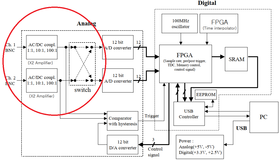
But I cannot understand what it is for (in which part of the signal acquisition block diagram) the CD405xB CMOS Single 8-Channel Analog Multiplexer / Demultiplexer is involved.

Thank you very much for reading me.
Greetings.

  • What signal acquisition block diagram? Do you have the schematic?

  • Good Morning!

    Thank you very much for the response and your interest.
    That is precisely what I am looking for, a schematic to understand well what the function of the MUX is in an oscilloscope.
    I can see from the photos that it is just in the first stage of entry.

    Thank you!
    I await your ideas

  • That box labelled "switch" needs some analog switches, and I guess that those amplifier blocks use analog switches to route the signal through different resistors.

  • Good morning, I have been doing a little more research on the subject.
    I see that "coincidentally" there is an OpAmp in each Mux, HRA and H2F.
    I understand they are used to first convert the "single" input to differential. And I guess another one for gain and / or filter.

    But is there any way that you usually do it? I can't see where the MUX is placed in this scheme.
    In other words, if we use, for example, to select the gain resistance in the feedback of the amplifier, we will have an error value caused by the resistance of the MUX, which can be very damaging in an instrumentation gain.
    So, does it go "before", "after"?

    Greetings! Thank you very much for this interesting debate.

  • There are ways of minimizing the effect; see SLYT612 and MT-088.

    I do not know how the designer of this device chose to implement this.

  • Hello,

    What is your interest in learning the placement of the mux in this system? Are you interested in designing a similar system?

    I can provide insight into information about TI's muxes and signal switches, such as CD4052B, or help you select a mux for a new design, however I am not familiar with how this specific board was designed with the CD405xB.

    Best regards,
    Kate

  • Thank you very much for your answer.
    These days I have been studying the documentation provided and it is very interesting.
    It has helped me learn various ways to make a gain selectable and find the reason for these devices in analog signal acquisition.
    I found the schematic of a similar digital oscilloscope that made me understand it even better.

    Still, I find the route they take crossing each channel a bit complicated. Above all, I am confused by the opamps that control the range.

    Therefore the answer to the main thread question is resolved:

    One mux adjusts the gain and another adjusts the measurement range.

    After this, new questions are opened to me ... Is it the correct way to do it for greater accuracy? According to the documentation provided, there are ways to reduce the effect of Ron, but, Is it still the solution adopted in professional oscilloscopes?

    Greetings.

  • Thank you very much also for your response.
    Actually, as I mentioned in my first post, it is an oscilloscope that I have at home.
    As a student and a fan of electronics I am, I did not resist opening it to identify each part. And I was surprised to see that part of the circuit that I didn't understand. I really like learning about these things.

    In fact, I raised a circuit for a Wheatstone bridge a while back based on TIDUB00 using an INA instrumentation amplifier. This document cites the need for great precision in the gain resistor. That is why it raises the question of whether a switch-based method to change the gain in signal acquisition is correct.

    Greetings.

  • This video might be interesting for you: EEVblog #675 - How To Reverse Engineer A Rigol DS1054Z (mentions TL072, CD74HC4053, TLV274)

  • Hello,

    Thanks for that information. I am happy to hear of your interest in electronics and how TI components fit into these systems.

    I am not specifically familiar with the design of professional oscilloscopes, but I can suggest two precision muxes with lower Ron and lower leakage current, which can offer improvements in this application - TMUX1109 and TMUX1108. The datasheets include some application information that you may find useful in your search.

    Best regards,
    Kate

  • This guy is amazing, I learn a lot in each of his videos.
    In fact, I am registered in their forum, but the answers are not as precise, professional and useful as I would like for some topics. So I turn to Texas. ;-)

    Too bad it doesn't go so far as to explain the gain setting for the differential amplifier on that oscilloscope.

    Thank you!

  • Wow!! Only 1.8 Ohms!

    But will it be small enough to make an array of gain resistors for an INA, for example?

    Thank you!!

  • Hello,

    While this may depend on your system, low-Ron muxes such as these are typically our best recommendation for precision gain control. 

    Additionally, these devices may be used to multiplex multiple sensors to an ADC, due to their low leakage current for improved system accuracy.

    Thanks for your interest in systems with TI components! I'd also like to point out our extensive resources on TI.com for designing many systems across industries. You can find end equipment reference designs, including block diagrams, schematics, and device recommendations in the "Applications" and "Design resources" tab on TI.com.

    Best regards,
    Kate