This thread has been locked.

If you have a related question, please click the "Ask a related question" button in the top right corner. The newly created question will be automatically linked to this question.

CD4051B: Switching between three coils using a Chipkit mx4 pro

Part Number: CD4051B
Other Parts Discussed in Thread: TS12A12511

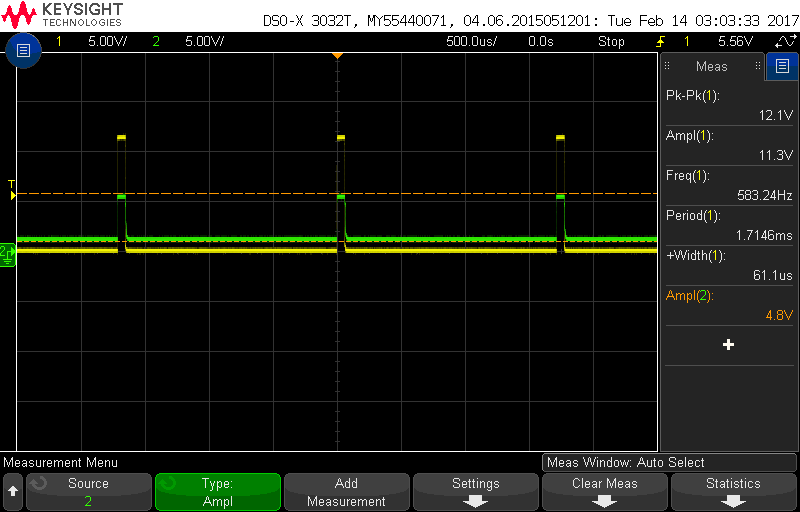
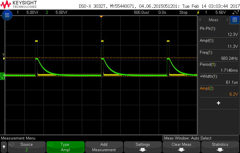
I was looking for some advice on a chip I have been trying to use for my senior design project called the CD4051B. So we are trying to send a pulse through the chip and have it switch between three loads consisting of three coils; we only want one load at a time on while the other two are off. We are currently using a micro-controller with an output of 3.3V as the select lines of the chip and a supply voltage of 5V to the chip's Vdd. Currently the issue we are having is that the output does not match the input, there are losses, and the channels that are supposed to be off are not completely off. I will attach the pinout below as well as pictures of the output I am getting. The answers I am looking for is how do I drive those signals down to zero instead of the decaying signal I am getting now and is there a way to avoid these losses. The details of the pulse can be found in the oscilloscope pictures below. I only need three channels so I connected the third select line to ground; the third image shows how I am connecting everything.

Yellow=input, Green = output "ON"

Yellow=input, Green = output "OFF"


  • Hello Andre,

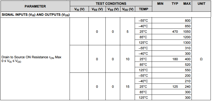
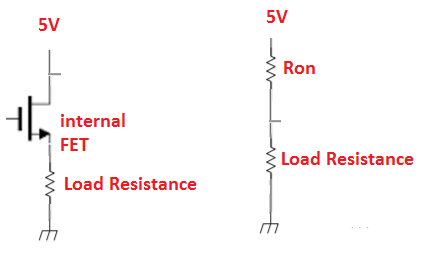
    One possible reason that your output does not match the input may be a result of CD4051B's drain to source ron resistance shown in the table below.  The parasitic resistance of the internal FET channel forms a voltage divider with your load resistance.  As you can see from the table below the typical ron at room temperature with a 5V supply can be quite significant (470Ω typically and as high as 1050Ω).  So if your load resistance is less than 10x this internal resistance, you will see significant losses.  Since you probably cannot choose your load resistance, if this is your problem, you may want to consider using a different part with a smaller Ron.

    Table 1 

    Figure 1

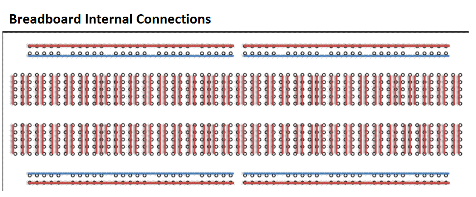
    As for the issue of your off channel passing a signal, I suspect the following. The bread-boards internal connections on the sides are not continuous and its possible that part of your ground is actually detached from the supply ground and thus floating.  The figure below should help make this clear.

    Figure 2

  • Hello Patrick,

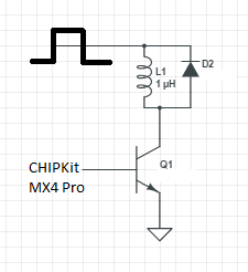
    Thank you for the timely reply. I think the issue is that my load resistance is only about 1.5 ohms (L=350uH) so I need to find a different part to switch between the three loads. Do you have any recommendations? I was looking into using transistors and turning them on and off with the microcontroller but there are so many out there to choose from I have a hard time finding what I need. I know the turn on voltage needs to be 3.3V (Vg-Vt) from the microcontroller and the transistor needs to be able to pass the 12V pulse with little to no distortion. I was thinking something like the following:

    When the switch is on current will flow through the coil to ground and when the switch is off the diode will help drain the stored charge in the coil. Am I going about this correctly? What diode and transistor would be a good fit?

  • Hello Andre,

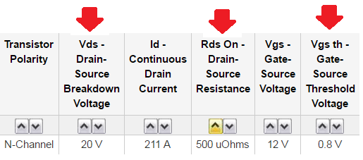
    The best TI part I can recommend would be the TS12A12511.  This permits a 12V signal through the channel (recommended operating conditions) and has a relatively low Ron (5Ω typical).  However, with this part you probably will still suffer from a larger voltage drop across than you would like.  So as you stated, you may want to use discrete transistors.  Below is a figure that illustrates the key parameters I would search in part supplier's website.  

    Figure 1

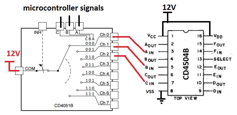
    Yet another alternative you may consider is using a switch followed by a level translator like the one seen in Figure 2.  However you will need to make sure that trough of your input signal to the translator is close enough to ground to ensure it does not result in a high output signal being generated at its output.

    Figure 2

  • Hello Patrick,
    So just to follow up with you I have decided to go the transistor route to avoid adding more power supply to they system. I have been looking everywhere online and I have found the following part that I believe has all the parameters for my application but I was looking for some verification from an expert.
     I guess the two major concerns I have are:
    1. Can I turn this transistor on and off with a 3.3 DC voltage (I measured and it is really only 3.17V) from a microcontroller?
    2. Can it pass a 12V pulse with a frequency of 580Hz with minimal loss and distortion?
    From the data sheet I believe these parameters are met and I know that the Ron is low enough so that there will not be a large voltage drop across the transistor. This is a link to a visual representation of what I want. http://tinyurl.com/zzzdl3s In this simulation the transistor is behaving in an ideal fashion. I wanted to try to run a simulation with this part on multisim but could not find it so I am seeking your advice. Is this a good fit for my application?
    Thank you.
  • Hello Andre,

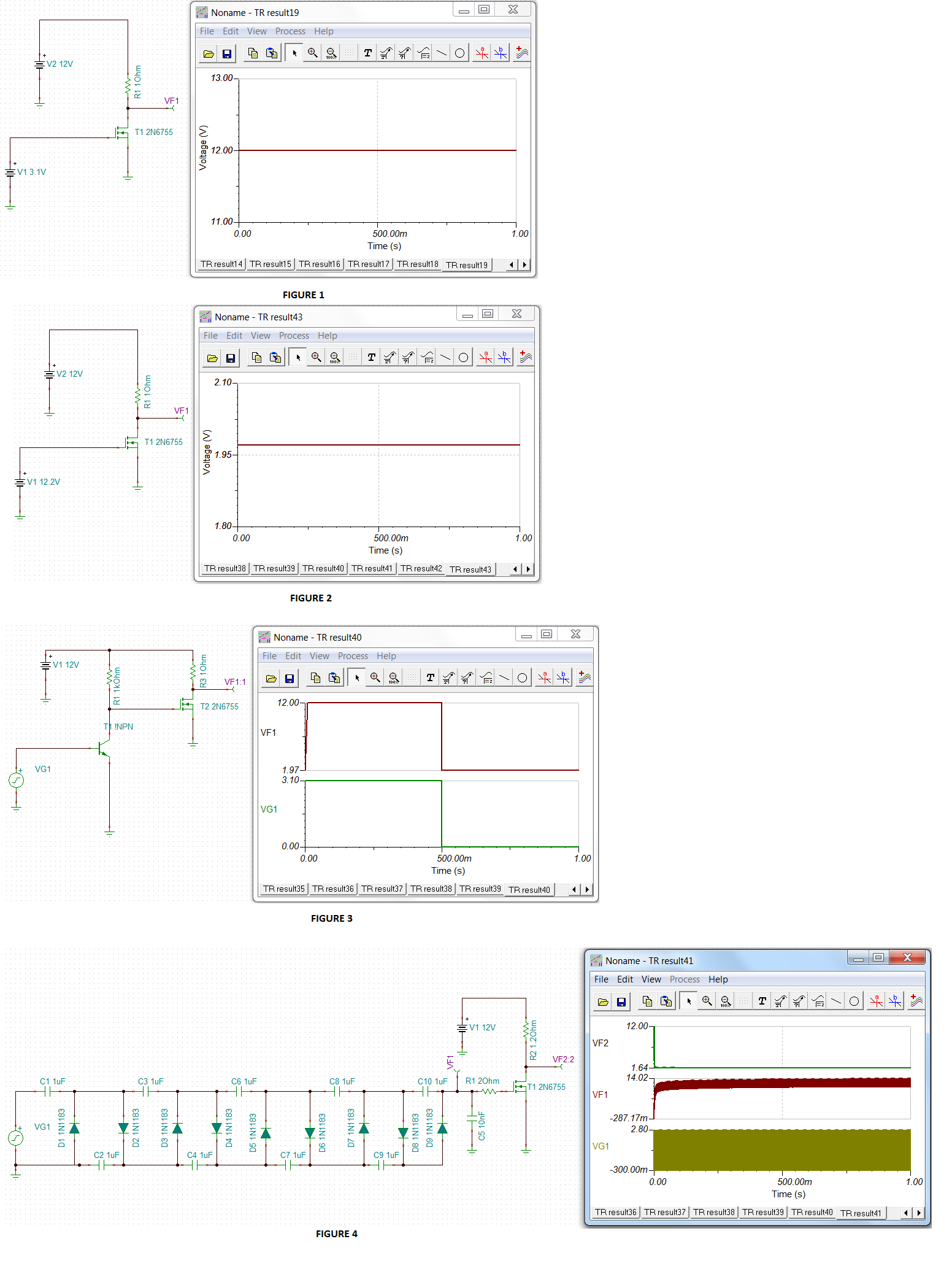
    I suspect without doing some voltage conditioning of your arduino signal, you will not be able to properly operate the MOSFET in the saturation region and have it perform as a switch.  From the Figure 1 below you can see that 3.1V voltage is insufficient to turn the mosfet on.  However if we increase the voltage such that it is above 12 V or the VDS value for when the NMOS is initially off, we can turn the NMOS on FIGURE 2.  Below in Figure 3, I am using a totem circuit drive the gate of the MOSFET. Yet another method can be seen in Figure 4.  This utilized a cockroft walton circuit and would require you to supply spurts of higher frequency signal (>>580Hz) that  you could utilize to turn on the gate.  Alternative approaches my include gate drivers and possibly a boost.