Hi All,
Customer has an application that uses SN74CB3Q3245, the block diagram is as below. Two slot board, each has a SN74CB3Q3245, and they have a back board, the output of the SN74CB3Q3245 is connected together to control the hard disk power, normally one is as control signal, another is for reading back. Each board can be read board or control board.

So questions are as below,
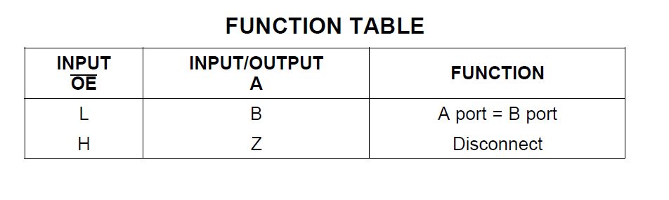
1) can SN74CB3Q3245 support bi-directional communication?
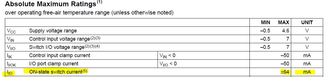
2) If two board are both configured as control board, one is sending high, and one is sending low, that means one SN74CB3Q3245 is outputing high level, another is SN74CB3Q3245 is outputing low level, and they are connected directly, will this cause damage to the two devices.
Best Regards
Charles Zhang