This thread has been locked.

If you have a related question, please click the "Ask a related question" button in the top right corner. The newly created question will be automatically linked to this question.

TS3A4751: Crosstalk in SPI bus switching

Part Number: TS3A4751

Hi all,

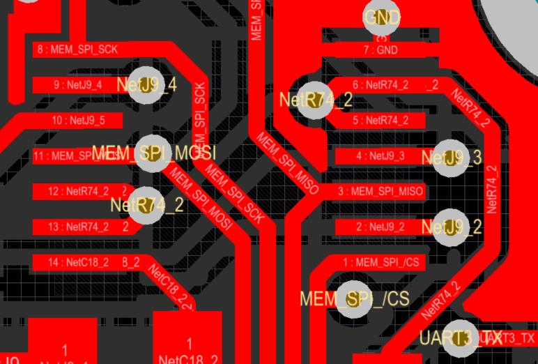
I have mounted TS3A4751PWR to switch a four-wire SPI bus to switch a FLASH  memory to a graphic controller (RA8875). It looks like I may have a crosstalk issue in the switch circuit. my graphic controller can properly read images from the memory when I remove the switch and the memory directly to the graphic controller. Same procedure with the switch in series, and the image read by the graphic controller is noisy.

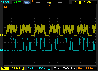
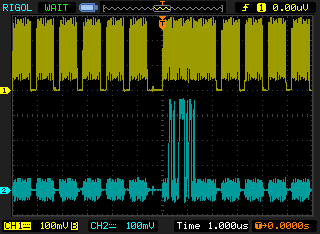
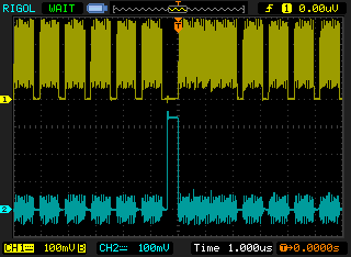
I can observe noise in the high frequencies of the picture (noise on the pixels' high freq). Noise is consistent with crosstalk from clock line to data line. is this hipothesis plausible? Please find attached a CAD capture.

SPI bus is running at 45 MHz.

Best regards.

  • Hello Albert,

    Could you please give us a little more information:
    1) What Vcc are you running the switch at?
    2) Can you ensure that the switch is turning on/off properly to ensure there is no bleed through?
    3) What bypass capacitance value are you using?

    Thank you,
    Louie
  • Dear Louie,

    1)Vcc is 3.3V

    2)The switch is always enabled (Four INx to VCC via a 10R resistor.

    3)A 100 nF decoupling capacitor.

    Best regards.

  • Hello Albert,

    Could you highlight the traces where the clock and the data line is in the screen shot you have posted above?

    Could you also provide us with some scope captures to better allow us to assist you?
    We would like you to probe:
    1) the GND point closest to the data line where you are seeing the high frequency noise (with and without the switch)
    2) the data line itself (with and without the switch in place)
    Please have the SPI clock present in all of the captures above.

    Thank you,
    Louie
  • Hi Louis, I'm Kevin and I'm working with Albert in the same project. I will provide you with the things that you request.

    First, I highlighted the traces with their names that run through the switch:

     .

    Second, the following captures are before the switch:

    - CS line:

    - MISO line:

    - MOSI line:

    Third, the following captures are before the switch:

    - CS line:

    - MISO line:

    - MOSI line:

    The result is shown in the next picture, where you can see pixels that are not display correctly:

    Thanks for your time.

    Regards,

    Kevin.

  • Hello Kevin,

    Could you please clarify which set of scope captures are with the switch and which are without?
    How are you probing these signals?

    Could you please provide me with the scope capture of the nearest ground point to the signals?

    I was looking at the the MISO line from your "third" section. There are some strange spikes that happen in your system which didn't occur in the "second" section.

    Could you provide a more zoomed in version of the captures and try to keep everything at the same scale for comparability purposes.

    My theory is that there is some noise in your GND's near the device and the signal path which is coupling into your system.


    Thank you for providing us with these, and thank you for your patience.
    Louie