This thread has been locked.

If you have a related question, please click the "Ask a related question" button in the top right corner. The newly created question will be automatically linked to this question.

TIDA-00120: Required Design changes for 48V System

Part Number: TIDA-00120
Other Parts Discussed in Thread: CSD19531Q5A, CSD19532Q5B, CSD18502Q5B, MSP430F5132

Hi,

I am using TIDA-00120 reference design for MPPT solar Charge controller.

As mentioned in the test results of TIDA-00120 i tried to upgrade the design to 48V system by changing the MOSFETs to 100V.

Changes made : 
1. CSD18532Q5A is replaced with CSD19531Q5A
2. CSD18502Q5B is replaced with CSD19532Q5B.
After the above changes, we found the following.
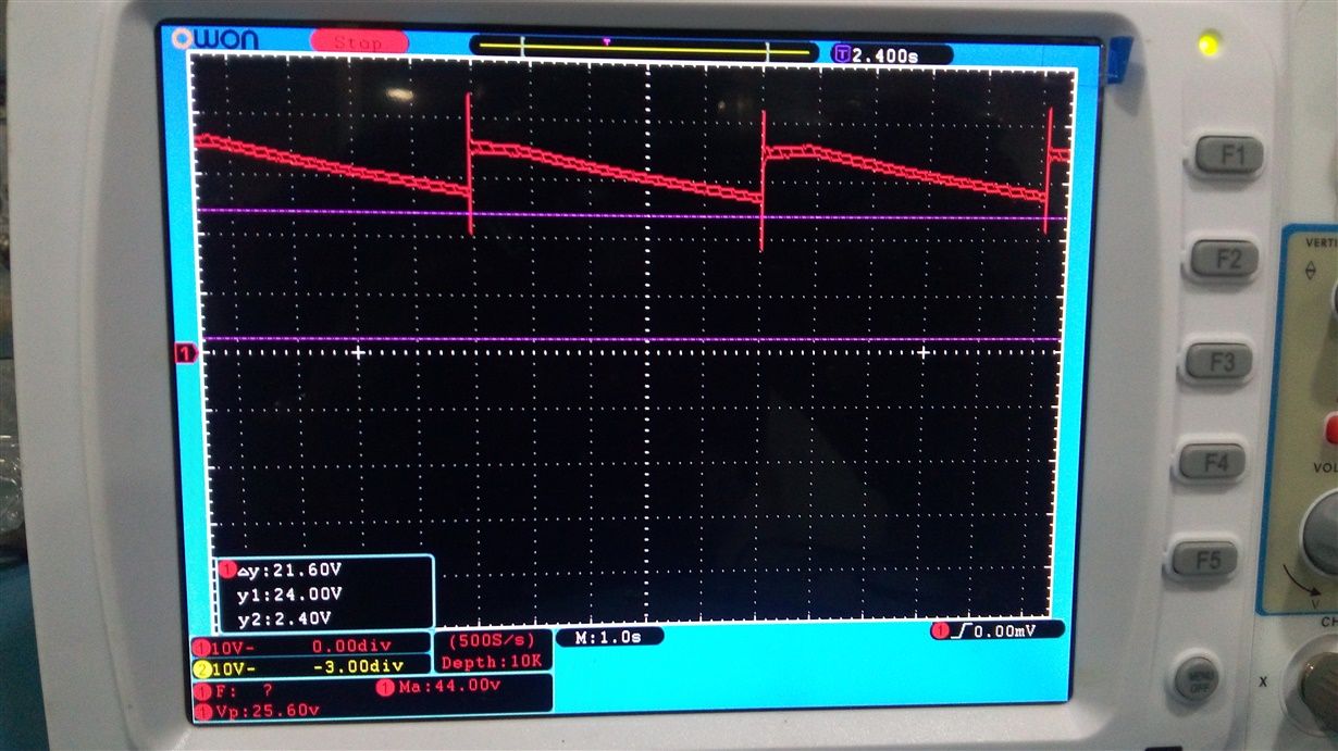
At No load condition: 
1. The output voltage  is reaching to 35VDC when the input voltage is 45VDC.(Please look at attached waveform)
2. The output voltage is slowly decreasing to 0V when the input voltage reaches above 45.5VDC
Is there any changes required in the design or Source code? Please help
regards
Naresh
  • Someone Please help me in this design

    regards
    Naresh
  • Naresh,
    No additional changes should be required in the hardware.

    In the software, the default value of "Duty" is 210, which sets the starting voltage of the output. Without a load, the system will attempt to track to a maximum power point, but with have no current, the measured power is 0, and it will keep tracking down to zero as you have seen. You can review the source code to see more detail on how the algorythms work.

    The software will need to be changed to be configured for your specific battery. See lines 125 to 131 in main.c.

    Regards,
    Bart
  • Bart,

    I have these lines in the code from 125 to 131 lines

    Init_Clocks (); // Initialize clocks for 25 MHz
    while (!POWER_GOOD);

    _delay_cycles (25000000); // ??


    // Initialize parameters from GUI

    Please advice me changes i need to do

    regards
    Naresh
  • You might have an older version of the firmware code. Please download the latest version from the design page to make sure. The firmware source code will be in a folder in the install directory and can be imported into CCS.

    You should see a section that looks like this to change for your battery:

    /**********************Needs to be changed with different Batteries************************************/
    unsigned int CC_LIMIT		=	300;				// 210 - 10A, 300 - 15A, 350 - 20A
    unsigned int CC_TO_CV_LIMIT	=	305;				// 305 - 14.2	, 610 - 28.4
    unsigned int FLOAT_VOLTAGE	=	295;				// 295 - 13.8	, 590 - 27.6
    unsigned int BATTERY_CUTOFF	=	220;				// 220 - 10.2	, 440 - 20.4
    unsigned int BATTERY_RECONNECT  =       240;				// 240 - 11.2	, 480 - 22.4
    /******************************************************************************************************/

  • TIDA-00120_Firmware.rar

    Bart,

    I got the latest firmware code(attached here).  I am not aware of the firmware. Please advice the changes in the firmware to modify the system to 48V

  • Naresh,

    Please get the latest source code release from the design page here: http://www.ti.com/tool/TIDA-00120

    You should be able to easily find the section I mentioned earlier to modify for yoru battery.

  • Bart ,

    I got the same code from the design page. I need to connect four batteries in series(12V+12V+12V+12V).

    /**********************Needs to be changed with different Batteries************************************/
    unsigned int CC_LIMIT = 300; // 210 - 10A, 300 - 15A, 350 - 20A
    unsigned int CC_TO_CV_LIMIT = 305; // 305 - 14.2 , 610 - 28.4
    unsigned int FLOAT_VOLTAGE = 295; // 295 - 13.8 , 590 - 27.6
    unsigned int BATTERY_CUTOFF = 220; // 220 - 10.2 , 440 - 20.4
    unsigned int BATTERY_RECONNECT = 240; // 240 - 11.2 , 480 - 22.4
    /******************************************************************************************************/

    Here i guess CC_TO_CV_LIMIT, FLOAT_VOLTAGE, BATTERY_CUTOFF and BATTERY_RECONNECT are mentioned for 12V and 24V systems.

    With these changes can this MPPT works for 48V system? Please confirm

  • Bart,

    Till now i didn't connect the batteries, i am just measuring the open voltage at BAT+ and BAT- terminals.

    Can i check the output by connecting the batteries to MPPT?

    Please confirm

    regards
    Naresh
  • Naresh,

    For the 48V system, these parameters will need to be set. In the comments are just some examples for 12 and 24V systems, but they illustrate how to scale the raw volt or amp measurement to ADC codes, which you will need to do for your batteries specific parameters.

  • Bart, 

    Is this correct for my  four (12V, 65Ah) lead acid batteries connected in series?

    /**********************Needs to be changed with different Batteries************************************/
    unsigned int CC_LIMIT		=	300;						// 210 - 10A, 300 - 15A, 350 - 20A
    unsigned int CC_TO_CV_LIMIT	=	1220 ;					// 305 - 14.2	, 610 - 28.4
    unsigned int FLOAT_VOLTAGE	=	1180 ;					// 295 - 13.8	, 590 - 27.6
    unsigned int BATTERY_CUTOFF	=	880	;					// 220 - 10.2	, 440 - 20.4
    unsigned int BATTERY_RECONNECT = 960 ;						// 240 - 11.2	, 480 - 22.4
    /******************************************************************************************************/
    

    regards

    Naresh

  • Naresh,

    Your values come out to the following voltages:

    CC_TO_CV_LIMIT 56.8
    FLOAT_VOLTAGE 55.22
    BATTERY_CUTOFF 40.8
    BATTERY_RECONNECT 44.8

    They seem reasonable for a 48V stack, but you will need to validate them against the datasheet of the batteries you are using.

  • Bart,

    I will check my battery datasheet and i will adjust according to the spec. Please let me know how you converted the above values. So that i can change the values as per my specifications.

    regards
    Naresh
  • Bart ,

    Please tell me how to convert the above values.

    regards
    Naresh
  • Naresh,
    It's a simple linear relationship to convert the voltage to the ADC codes and back. You can use the values in the comments to extrapoalte to the new ones.
  • Hi Bart,
    I have done below changes in my code and i have given PV connection to my MPPT. (Battery not connected)
    /**********************Needs to be changed with different Batteries************************************/
    unsigned int CC_LIMIT = 300; // 210 - 10A, 300 - 15A, 350 - 20A
    unsigned int CC_TO_CV_LIMIT = 1220 ; // 305 - 14.2 , 610 - 28.4
    unsigned int FLOAT_VOLTAGE = 1180 ; // 295 - 13.8 , 590 - 27.6
    unsigned int BATTERY_CUTOFF = 908 ; // 220 - 10.2 , 440 - 20.4
    unsigned int BATTERY_RECONNECT = 960; // 240 - 11.2 , 480 - 22.4
    /******************************************************************************************************/
    My PV Specifications:
    Power = 70W
    Voc = 43.02V
    Vm = 36.04V
    Im = 1.95 A
    I have connected two panels in series.
    After that some of the components in my board got damaged. (MSP430F5132, SM72295MA and CSD19531Q5A(Q2,Q3,Q4,Q5) ).
    I have replaced those components and i have tested again with my regulated DC source as input. Then my board was working fine with 12V and 24V system(With and without battery)
    After that i removed my batteries and  increased input voltage to 70VDC, then again MSP430F5132 got damaged.
    Why  is this happening? Is there any modification required in the design ? Please let me know
    regards
    Naresh

  • An input of almost 90V will be quite high, even with 100V FETs. Keep in mind that there will be inherent overshoot that could damage the FETs and associated circuitry. If you probe the switch node, you should be able to measure these overshoots.

    Check out the document here on proper ways to measure and mitigate overshoot: e2echina.ti.com/.../8244.Ringing-Reduction-Techniques-for-NexFET-high-performance-mosfets.pdf
  • Bart,

    While i am testing for 48V system  i have given 70V input supply from the DC source without connecting any Load/Battery. At this situation MSP430F5132 got damaged. What would be the reason for this?   I made some changes(marked in attached files) in the schematic after this situation. Please look into attached picture(MPPT Schematic_2) and let us know whether it is correct or not.  

    When we tested the board for 36V System, we have connected three batteries in series(12V, 65Ah). At this condition the input voltage is 52VDC. The MPPT has worked with charging current of 5A . After 5 minutes two mosfets Q4 and Q5 got burnt. What would be the issue?

    Here i am attaching the wave forms of 36V System at No load condition for your reference. Please check it

    regards

    Naresh

  • Bart ,

    Please suggest me the solution for my problem.

    regards
    Naresh
  • Hi Bart,

    Is there any solution for this? please let me know

    regards
    Naresh
  • Naresh,

    Bart is back in office on Thursday and will get back to you on this query.

    Thanks,

    Jayanth 

  • Naresh,
    With the voltage divider changes you made to the ADC inputs, the ADC is now seeing 4.84V when the panel input is 48V. This could easily damage the device as it has a 3.3V input range. The existing 10K resistors used for that divider would allow for a panel voltage up to 60V, and the software scaling factors would still be correct. With that change, the parameters in the source code would also have to be fully recalculated to the new range.

    On your scope captures, could you label the traces so I can tell what signals you are probing?

    Regards,
    Bart
  • Bart ,

    I changed the divider network after my device got damaged. After my changes i measured the voltage at ADC inputs as 2V when the panel input is 70V. 

    Please tell me what are the parameters i need to change in the source code.

    Please find the attached pictures for your reference. If you want verify any other signal please let me know so that i can share you 

    regards

    Naresh

  • Ah, I missed that you also changed the high side resistor as well. At a panel input of 70V, the existing divider will would defiantly not be sufficient.

    The software is just using ADC readings in it's calculations. When you change the voltage divider, the ratio between the actual voltage and the ADC input is changed, so the ADC code will not align with the same input voltage as it used to. You will need to determine the new ratio, and then the new values for the settings you changed previously. Otherwise, the software may attempt to track to a voltage that is incorrect and might damage components.