This thread has been locked.

If you have a related question, please click the "Ask a related question" button in the top right corner. The newly created question will be automatically linked to this question.

TIDA-00527: TIDA-00527

Part Number: TIDA-00527
Other Parts Discussed in Thread: TIDA-00057

hi

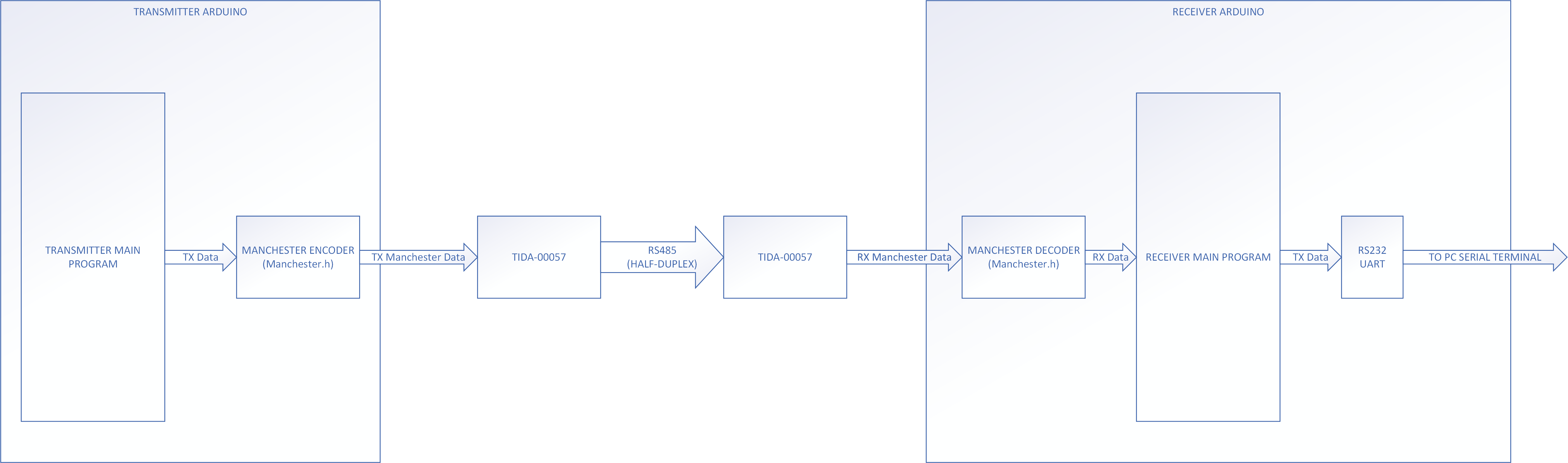
Can anyone help with Manchester coding.

I am using Manchester.h library from Arduino and try to send data serially and passing though TIDA00527 and receiving from other end using arduino serial.

The problem I am facing is the data I am getting data at receiver end continuously but the bits I am sending is different in code and what actually I see in serial monitor for transmitter

Below is the simplified code

#define TX_PIN 1

void setup() 
{

man.setupTransmit(TX_PIN, MAN_9600); 

}
void loop() 
{

man.transmit('0');

}


This is transmitting code from my arduino using Manchester.h library. But i am not able to get how the 0 is sending in form of garbage i am receiving at the terminal how can i decode it..? I am getting this at the termianl

Y⸮⸮⸮Y35⸮Y3⸮⸮Y⸮u⸮Y35⸮Y35⸮Y⸮⸮⸮Y⸮⸮⸮Y3⸮⸮Y3⸮⸮35⸮Y35⸮Y⸮⸮⸮Y⸮⸮⸮Y⸮5⸮Y3⸮⸮Y⸮⸮⸮Y35⸮Y3⸮⸮⸮5⸮Y35⸮Y⸮⸮⸮Y⸮⸮⸮Y⸮⸮⸮Y3⸮⸮Y3⸮⸮35⸮Y35⸮Y⸮⸮⸮Y⸮⸮

  • A couple simple questions first- 1) Have you verified that the baud rates are configured the same for both the transmitter and the receiver?  What about the baud rate between the receiver and your terminal monitor?  2) Where is the Manchester data decoded?  Is it getting decoded in the receiving Arduino and then re-transmitted to a PC based serial terminal?  Have you setup your receiving Arduino to decode Manchester data properly?  I don't use Arduino's myself so I'm not adept at using them, but I assume that since this is Manchester data, you are using a software "port" to send/receive the data since I don't think the hardware UARTs on the Atmel chips are capable of encoding/decoding this type of data.  Do you have the libraries configured for the proper clock speed and does it match the speed your hardware is running at?  (is that even configurable on and Arduino?)  Do you have some other loop/code that could be blocking your receive routine and preventing it from receiving the data properly?  You might try introducing a delay between characters on the transmitter to allow time for the receiver to capture, process, transmit the data to the PC.  This will hopefully keep the receiver synched with the transmitter.  If it even missed one bit, but the data kept coming, you'd see garbage.  That's why serial messages are typically wrapped in a packet form so that the transmitter and receiver can try and stay synchronized.

    3)  Have you checked the power supply rails are stable at your receiver?  Check them with an O-Scope since a DMM won't be able to capture fast dips in the rail.  Provide plots if you're able to.  Remember when using a distributed power system like the PoE - the supplies now have a high output impedance at AC frequencies.  This means that proper use of decoupling capacitors and distributed bulk capacitance is important at the receiver side to restore a low supply AC output impedance and eliminate HF power supply ripple on the receiver side.  Significant ripple on the receiver could interfere with the RS485 transceiver and/or your Arduino.

    4) Can you also provide scope plots of the serial data leaving the transmitter and entering the receiver, (X,Y and A,B terminals).  Signal integrity issues could be the culprit and scope plots will help diagnose that.

    Shawn

  • Hi Divyanshu,

    I agree with Shawn's excellent feedback above.  One quick test you could consider would be to bypass the AC-coupling capacitances and connect the differential transmitter output directly to the differential receiver input.  If communication works there then you would at least know that there is not a software configuration issue.  In that case scope shots at both ends would be very valuable to help debug.  I mention this because the use of AC-coupling capacitances in this reference design limits the minimum data rate that can be achieved.  Best results are generally at 1 Mbps or greater;  from your code it looks like a baud rate of 9600 bps may be used.  The use of Manchester encoding will certainly help by ensuring average DC balance, but there will still be a limit below which the signal decays too much within each Manchester "bit."

    Max

  • Hi

    1.The baud rate are same for tx and RX of controller. Same for serial terminal and computer.

    2. How can i decode it if i am not able to get what is going in terminal at transmitter type. Its showing garbage while sending 0


  • 1)  That's good that the baud rates match.  Always got to ask/check the basics first.

    2)  I assume that a block diagram of your system looks similar to the following:

    When the transmitter formats the data using Manchester encoding, it uses special symbols to represent a binary 0 or 1.  It uses a transition from high to low in the center of the bit period to indicate a 1 and a low to high in the middle of a bit period to indicate a 0.  This encoding must be reversed (decoded) by the receiver in order to extract the original information that was sent.

    In your example code you provided you used man.transmit('0'); to send your data from your main program.  I assume that this function takes the argument that you passed to it and shifts it out one bit at a time using Manchester encoding.  On your receiver, there should be an equivalent type function, man.receive(); or similar that watches a pin for transitions and decodes the data back to regular binary. (I have no idea what the proper syntax is as I've never used the Arduino libraries.  You should refer to the supplied API documentation to get the proper syntax and function name.)  You cannot pass the RX data out of the TIDA-00057 on to the PC without first running it through a Manchester decoder.

    To troubleshoot your issue, we need to break the whole thing down.  First, where are we on being able to get O-scope captures of the output and input waveforms of the RS485 bus?  Once we verify the hardware channel is good, then we can proceed to investigating software type issues.  Max made some excellent points about minimum baud rates being required due to the AC termination scheme used at both the transmitter and receiver.  So if you see distortion or significant changes to the waveform at the RX side, simply try increasing the baud rate between the transmitter and receiver and see if the data starts coming through better.  Again, I'd suggest slowing down the message rate in order to give the receiver a chance to process the data and retransmit it.  Since there are no hardware FIFO's that can be used for a software defined serial port, your receiver can only do so much before it starts missing bits (or bytes or words or even entire packets).  Try inserting a 1 second delay after each character sent to see if that helps.  (You can tailor the delay to speed your transmission rate after you get it working.)

    Shawn

  • Hi

    I am currently Sending data and i can receive it without the TI Circuit but when i put the TIDA00527 Then i faced some problem the below given,  the signal Tx is perfectly fine but there is a distortion in A, B . 

    Powerover_RS485.zip

  • Hi

    I am currently Sending data and i can receive it without the TI Circuit but when i put the TIDA00527 Then i faced some problem the below given,  the signal Tx is perfectly fine but there is a distortion in A, B . 

    3056.Powerover_RS485.zip

  • Hi Divyanshu,

    We'll consolidate our feedback into your other thread here:

    https://e2e.ti.com/support/tools/sim-hw-system-design/f/234/t/812997

    Max

  • Hi

    Better..waiting for ur reply