This thread has been locked.

If you have a related question, please click the "Ask a related question" button in the top right corner. The newly created question will be automatically linked to this question.

TIDA-00527: TIDA00527

Part Number: TIDA-00527
Other Parts Discussed in Thread: TIDA-010035, SN65HVD96

Hi

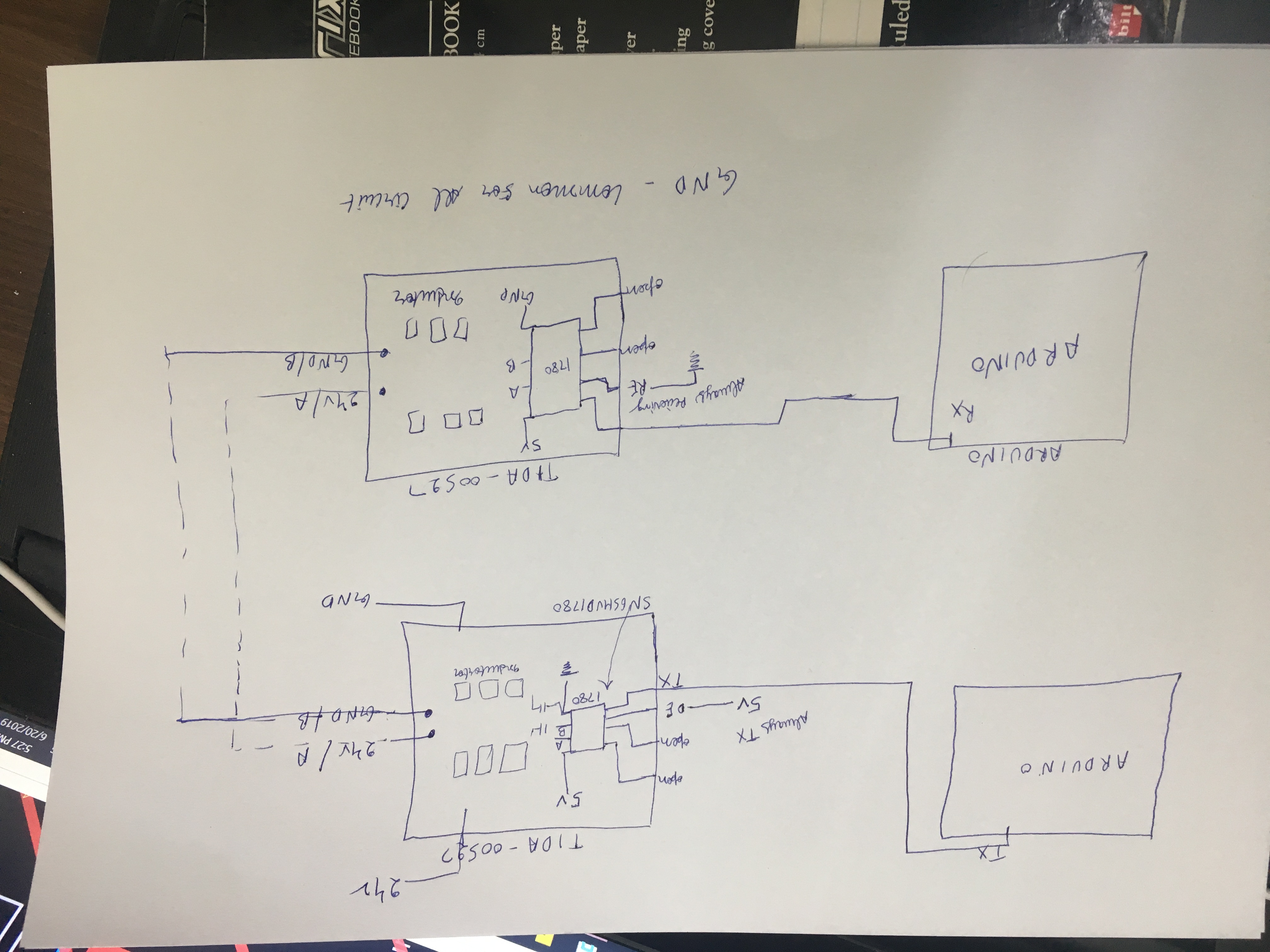
I am currently Sending data and i can receive it without the TI Circuit but when i put the TIDA00527 Then i faced some problem the below given,  the signal Tx is perfectly fine but there is a distortion in A, B . 

0830.Powerover_RS485.zip

  • Divyanshu,

    The problem is that your baud rate is very low (9.6 kbps).  This low-speed signal cannot make it across the AC-coupling capacitances used in this design (which act as a high-pass filter).  Instead, only the signal edges make it across and the waveform appears distorted.  The reference design was intended for higher-speed communication (~1+ Mbps).

    Is it possible for you to increase the baud rate rate significantly (100x)?  It would also help to increase the coupling capacitance values and the termination resistance values as much as possible (since these component values will determine the corner frequency of the high-pass filter created).

    Max

  • Hi

    I Tried with 115200 but I was unable to get the response at the receiver site

  • Did you see similar differential waveforms in that case?  I'd like to make sure it was a hardware issue rather than a software issue when increasing the baud rate.

    Max

  • Man, those scope captures sure do look like there is some heavy filtering going on.  It would be helpful possibly to see if the frequency dependence of the signal's integrity through the RS422 link.  Do you have access to a function generator?  If so, connect its output to the TX input on the transmitter.  Connect the DE input high to enable transmission.  On the receiver side, short the RE pin to GND and monitor the A,B inputs at the receiver with your scope just like before.

    Configure the function generator as follows.  Square wave output, 0-5V output, 50% duty-cycle, 10KHz frequency

    While watching A,B inputs at the receiver, increase the frequency of the function generator until you start getting a decent looking signal at the receiver.  When you get a clean signal at the receiver, round the frequency up to the nearest standard baud rate and that's the rate at which you will want your Arduino's to communicate at.  If the baud rate is too high for the arduino to use, then increase the value of C7 and C8 on the transmitter and receiver TIDA-00527 boards and repeat the function generator test.  You can also bump up the value of R1 at the receiver to lower the required operating frequency more.

  • The Inductor value from the different combination is 560uh.

    The decoupling capacitor are 10uf. and i didn't put the resistance of 120ohm before decoupling capacitor

  • You could refer to this app note for LC selection (equation 5 and 6 on page 11).

    www.ti.com/.../tiduei9.pdf

    Like Max and Shawn pointed out, the data rate is low. If you want to decouple it from the DC power supply, you could either increase the data rate or increase the capacitor values.

    Please let me know if it makes sense to you.

    Regards,

    Hao

  • The 19200 baud pics look a little better but that baud rate is still way too low.  Try running at 115200 baud or better yet 1000000 baud (1Mbaud) and see if that looks any better.  If the Arduino Manchester.h library doesn't support baud rates that high then you might have to consider increasing the capacitance values for the AC coupling.  If that is not an option then your only other options are using something other than the TIDA-00527 to power your receiver or use a processor with a little more horsepower than a simple Arduino.

    You also said that you took out the 120 ohm termination resistors.  You really should have some terminating resistance on the transmission line.  That will help clean up the waveform when you start running at these higher baud rates.  

    Shawn

  • Hi

    I can worked on 115200 baud rate can u suggest me any other controller on which u guys have worked the best way would be controlling the bit using hardware or software

    Moreover. I am not able to get the signal on my controller but i am able to get it on my DSO.

    Please look into the signal pic for reference.

    Output.zip

  • Hi

    I have taken Fmin  as 5khz and Zo = 60ohm. and find the inductor and capacitance value according to that. Will it fine for Signal transfer.

    Please look the signal as given to shawn may it help u out the next step for it.

    Waiting for ur reply

  • Hi

    Can u suggest any other power over Rs485 device for the same. 

  • EDIT:  Sorry, your other two posts didn't show up on my machine until after I hit send on this message below.  Please disregard this while I ponder what you're seeing.

    So what am I looking at in these most recent pictures you sent?  Are those captures of data in of the transmitting TIDA-0527 and data out of the receiving TIDA-0527's at a baud rate of 115.2K?  If so, that looks like the RS-485 link is functioning properly at that baud rate then.  If so, I believe you're saying that your problem now is that the receiving Arduino can't keep up at that high of a data rate?

    You have a couple choices here:  1) rewrite your sketch so that it runs faster on the receiver.  2) switch to a higher speed microcontroller in your receiver.  or 3) modify the AC coupling circuit on the TIDA-0527's to work with a lower baud rate.

    Results from 1) will vary depending upon how your code is structured and how well you can optimize it.  Does Arduino allow for mixing C and assembly?  You might have better luck if you can rewrite the Manchester decoding in assembly and put it in an ISR triggered from an interrupt-on-change of the RX pin.  Again, your millage may vary on how much of a speed improvement this will make in the receiver.

    Option 2) above may be possible, but will likely be a more expensive solution.  I'm not sure what Arduino package you're currently using in order to be able to recommend a better one.  Are you hard set on using Arduino or are you open to moving to totally different platforms.  Again, this will likely be a more expensive solution and I would only recommend it after all other options have been exhausted.

    Option 3) above is where I would start.  The white paper that Hao linked to above  is an excellent resource for evaluating component values for the AC coupling capacitors and isolation inductors.  See if you can work backwards from a baud rate that you know works with your current Arduino setup without the TIDA-0527's inline (i.e 56K? or 19.2K) to arrive at new capacitor and/or inductor values.  If they are practical values, then try swapping the parts on the eval boards you've got and see if the system now works at the lower baud rates.  This will likely involve larger values for both the series caps and the isolation inductors.  I haven't worked the math yet to know what they would look like for the lower baud rates.

    Shawn

  • Hi,

    Thanks Shawn's detailed explanation, which is so extensive that I don't have much to add. My comments about LC values are that you can get the proper value for your case by scaling the values in TIDA-00527 or TIDA-010035.

    Regards,

    Hao

  • Hi

    I have some queries like :

    1.Can u help me knowing the difference between Tida00527 and Tida010035. I can go with  if it works good than TIDA00527.

    2.moreover TIDA010035 have fixed capacitor and inductor value.

    3.Do i really need Manchester coding while sending the data. or it can be handle hardware only by making the bus busy sending 1khz wave.

    4.Do Sn65hvd96 also fits good for the same ...?

    I just need my RS485 signal on power bus, Suggest the best one out with good support

  • Hi,

    TIDA-00527 and TIDA-010035 address the similar application. TIDA-010035 does more system analysis in simulation. The LC values are chosen for the application in each design. You need to have a DC-balance signaling, which could be Manchester or 8b/10b or others. SN65HVD96 is special due it's receiver detection mechanism. For these two data over power designs, it's not necessary.

    Regards,

    Hao 

  • Hi

    For DC balance signaling. Can we generate a 1khz differential signal over the busbar. Because I’m actually condition the power bus will be idle.

    Using Manchester will help me while sending the data continuously busy when my bus is idle for that should I send a frequency generator to the bus.

    I didn’t get ur point for SN65HVd96 Ic... ?

    this all TIda 00527 TIda 010035  are the same application depending upon the application u choose the LC combination right.?

  • Hi,

    You can refer to this post about the DC balance.

    www.quora.com/What-is-DC-balance-in-communication-systems

    The main point is that the signal doesn't transmit the DC signal due to the AC coupled capacitor. If you have long 1's, the DC of the received signal could shift out of the receiver region.

    SN65HVD96 receiver doesn't function as a typical RS-485, which generates H no matter the differential voltage of A/B is positive or negative.

    Your last point is correct.

    Regards,

    Hao

  • Hi

    Do Texas provide some board for this application

  • Hi,

    Which board do you need? I thought you have TIDA-00527. There are no boards for TIDA-010035 since it's simulation based.

    Regards,

    Hao

  • Dear Sir,

    Sorry, I was busy.

    We had made a board of Tida-00527 as per the schematic. We don't have an actual board for this. Is there any way we can get the board for testing purpose...?

    We need to conclude upon this ASAP.

    If we can move towards the TIDA-010035. Will it work properly. Because it has an exact value for capacitor and inductor. Do u suggest me to move towards that board for the same...?

  • Divyanshu,

    Were you able to increase the signaling rate of your differential data transmission and introduce DC balance as suggested?  If so, may we please see the A and B signal waveforms on either side of the link to confirm?  I ask because none of these solutions would work well with low-speed, unbalanced data, and so without making this change it wouldn't make sense to try a different PCB.

    Max

  • Dear Sir,

    I am trying to make this application more towards the hardware compatible. As I have to put manchester coding .

    I am trying to balance dc by sending a 1khz wave on the bus line. and if any data will be sent and change in dc line may detect the data.

    I have seen many modules which they majorly giving the hardware compatibility irrespective of ur firmware.

    Can u help me in getting some better way for Dc balance? 

  • Moreover, I have seen many people didn't work on TIDA00527. Even its board is not available.

    Can u help me getting a launch board for testing purpose..?