This thread has been locked.

If you have a related question, please click the "Ask a related question" button in the top right corner. The newly created question will be automatically linked to this question.

TIDA-00524: Updated BOM for Revision A / Questions about Resonance Frequency

Part Number: TIDA-00524

Hello, I have a couple of questions on the evaluation board: 

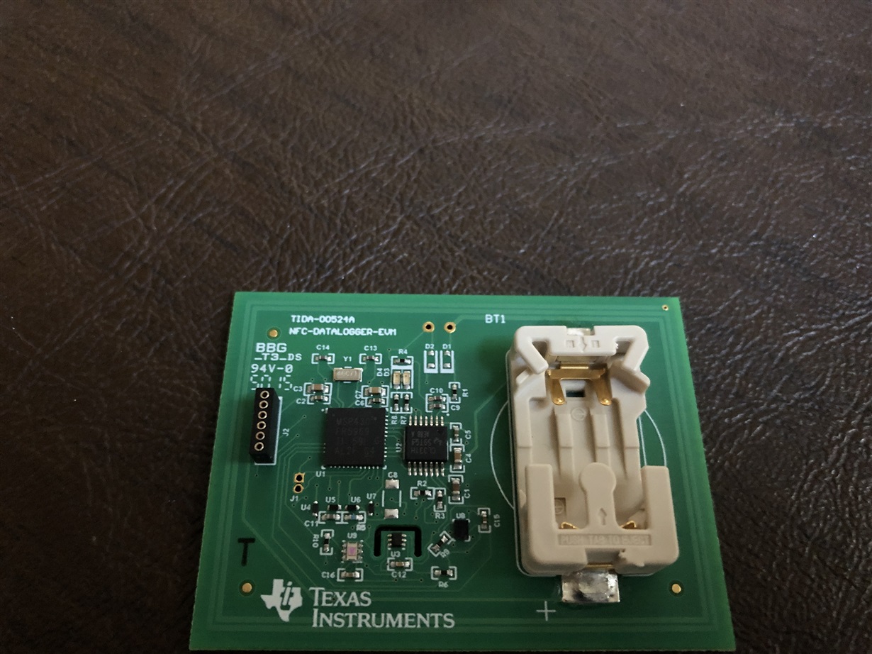
1) Comparing the BOM for the TIDA-00524 (Revision A) and the BOM posted online, both C9 and C10 are populated on the physical evaluation board. Please advise what the value of these components is. 

2) Verifying the resonance frequency of the assembled board, when the battery is not populated, it is ~13.03Mhz. With the battery populated, it is ~13.60Mhz. Please advise if the tag requires battery power in order for an accurate measurement to be made with a spectrum analyzer.  

3) Is there a documented measurement of the coil inductance?  

Thank you, 
Karl 

  • Hi Karl,

    Our experts will get back with you in the following week.

    Jalen

  • Dear Karl - 

    The BOM I looked at here does not have C9. Perhaps you are asking about C10 and C11. C10 is 35pF. See page 24 of the user guide here and regarding the tuned antenna, please see section 7.5 here in same document: http://www.ti.com/lit/ug/tidu821/tidu821.pdf

    Regarding the tuning with or without the battery - i think you have found that the tuning is correct when battery is in place, which makes sense, as this is a datalogger example, which needs the battery to perform the measurements and log data, without the magnetic field (from the reader) present. 

  • Josh - please find attached an image of the TIDA00524A board that I have. There is a C9 and C10 that do not match the schematic or BOM. I did not want to remove the capacitors to measure and risk damaging the original board. 

    I verified the gerbers from the same product page and they also contain c9/c10. 

    Is the detuning without the battery present due to draw from the uC or other components on the demo board?  

    Thanks, 
    Karl

  • Hello Karl,

    At one point because of how the EVMs were made (specifically part procurement...), the battery holder for boards had to be changed. I assume the design files for the TI Design wasn’t updated when that happened. I don't even have that version of the board myself, but I could compare it to mine easily enough.

    Based on my comparison, C9 and C10 on that board are equal to C10 and C11 on boards made based on the design files.

    Those are the antenna tuning capacitors as Josh alluded to, so his guidance here is accurate. The new battery holder changed the tuning values needed and so now two capacitors are used instead of one.

    The tuning does need to be done with the battery in place.

    We do not have a documented measurement of the coil inductance, we have never done this for any EVM because of variance in measurements on each PCB.

  • Ralph -

    Perfect, thank you for the clarifications. 

    Karl