This thread has been locked.

If you have a related question, please click the "Ask a related question" button in the top right corner. The newly created question will be automatically linked to this question.

WEBENCH® Tools/LM76002: LM76002 Pspice model example for TI website.

Part Number: LM76002

Tool/software: WEBENCH® Design Tools

Hello,

I downloaded LM76002_Non-Inverting_and_Inverting_PSpice_Transient_Model-A.

I am running the simulation for 45V input, 28V output for 2.5A, The RFb and other values I got form webench, I want to run simulation for my requirement.


Case 1) While i edit values of Rfb, L and output capacitors, simulation results are showing default only 24V input and 5V output.

Case 2) I took LM76002_Unencrypted_Pspice_Non-Inverting_and_Inverting_Transient_Model-A, I add .mod converted to .lib and .olb, Here model it not working.


Please find below images for case 1 and case 2.

I am using cadence 17.2

case1:

Case2:


  • Santhosh,

    Please attach the images again. They did not attach properly.

    You made a WEBENCH design with 45VIN and 28VOUT. Did you export the design from WEBENCH to spice or did you just take the component values? If you exported, the input and output voltages should not have changed. If you did not export, try exporting.

    -Sam

  • Santhosh,

    Have you had a chance to look at this? Please let me know if you are still experiencing issues.

    -Sam

  • Hello We have power supply design using WBdesign. Our requirement is 45v input, 28V output & 15V output also(15V output we are changing RFb resistors through analog switch), Can you please tell me this design will works or not?

    Here I am attaching my schematic image for the same.

    In this thread I have two quires one is simulation and other is my design validation.

    Can you please reply me both ASAP.  

  • Santhosh,

    1. Yes you can change the feedback resistors through an analog switch to change the output voltage. You can use the datasheet (and WEBENCH if you'd like) to verify that both output voltages will work with your specs.

    2. Your issue, as I understand it, is that the input voltage shows 50V but the node is at 24V, correct? Please attach your file so I can take a look and let me know how you got this file (export from WEBENCH?)

    -Sam

  • Hello Sam,

    Thanks for reply.

    1) Yesterday local TI technical person told, If use analog switch, It may go from 24V it will go 0V and then it will come 15V .

    Solution for this he suggested: First Disable IC EN pin & let it go 15v and then change feedback resistors.


    Can you please clarify how to use this and how it will work.

    2) I didn't import WEbench design, I downloaded example files from TI Pspice libray and I import those files and I changed buck steady state and buck start up.

    Here I am attaching two files of those,  First one is created form uncrypted Pspice model and second one is example of TI model in that buck converter I changed values... I am not able attach that because size is was morethan 20000KB.

    0066.LM76002 simulation-PSpiceFiles.zip

  • Hello Sam,

    I took WEbench orcad file from Export design, I follow the process of read me file..

    Here I am attaching readme file and exported simulation file.

    It is showing components can't simulate, I think design was just schematic only not simulated components.

    Can you please tell me how to do simulation, What is the process.

    4885.readme.txt
    To import your new Schematic into Orcad Capture CIS:
    
    1. Unzip the downloaded folder files to a local directory and 
       Start Orcad Capture CIS.
    2. Select File\Import Design from the menu.
    3. Select the EDIF tab.
    4. Browse to the correct EDIF file in the "Open" Window.  Note that it will not see
        the "edif " directory by default.
    5. Verify remaining settings.  If you do not have a configuration file already
       you can (and really should) use the one provided with your exported files.
    6. Press Okay.
    
    A Schematic will be imported for you.  Use File\Open\Design from the menu to view your Schematic.
    
    For additional information, please visit this site:
    http://www.accelerated-designs.com/help/OrcadCapture_BrdSch_import.html
    Orcad.zip

  • Santhosh,

    1. Changing the feedback resistors while the part is enabled will cause the IC to regulate from the previous voltage to the next voltage. I do not see a reason it would fall to 0V first. What is the name of the TI contact? I'd like to align with them.

    2. I was incorrect. I thought WEBENCH could export this part to spice but this part does not have that capability. So the way to simulate is the way you've done.

    I will get in contact with the spice team to assist you with your spice question. They will reply shortly.

    Thank you,

    -Sam

  • Santhosh,

    I should add, changing the output voltage on the fly will have a transient so 24V to 15V may undershoot. But the IC has negative current limit so this will be limited. It is best to try on an EVM to see real performance.

    -Sam

  • Hello Sam,

    Thanks for the reply- TI contact person Mahindra.

    I will check with him for EVM board and I will wait for spice team reply.

  • Hi Santhosh,

    Currently Spice modeling is looking into your request and get back to you in couple of days.

    Thanks for the patience.

  • Hi Santhosh,

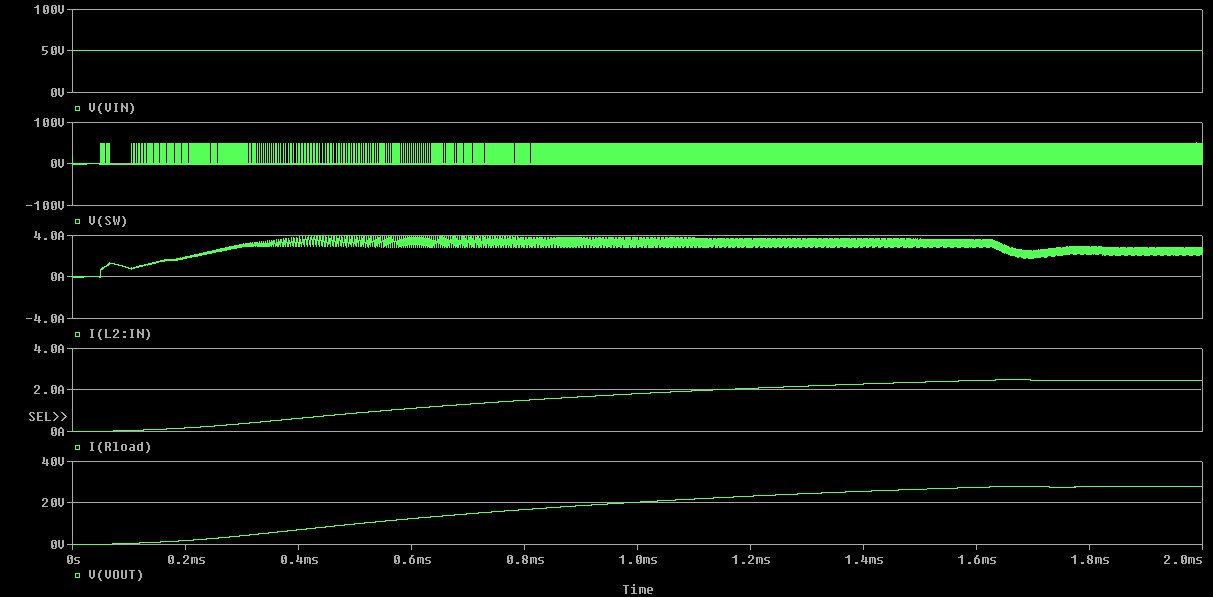
    For case 1: I simulated with startup schematic with the testbench you have provided. Please change the output load resistor to {28/2.5}. The load resistor you are using is causing the device to hit current limit, thereby reducing the output voltage. The same testbench using steady state schematic is causing convergence. I would suggest to use startup schematic for your test bench. Please find the results below:

    For case 2: Could you please elaborate on what you mean by it is not working? Also, could you please share the complete project. The size of your project is high as there is data file present in the folder. Please search for .dat file and delete it before zipping. Hope this helps.

    Regards,

    Karthik

  • Hello Karthik,

    I took model from LM76002_Unencrypted_Pspice_Non-Inverting_and_Inverting_Transient_Model-A.

    I convert this to .lib and .olb , I prepared simulation file, IC is not executing.

    Here I am attaching my simulation project.1185.LM76002 simulation.7z

  • Santhosh,

    Please follow up with us if your issue does not get resolved.

  • Hello Karthik,

    Could please give me the reply, I wanting for your answer.

    I need simulate my own circuit, I can refer Buck startup but I need to add analog switch on it and then I need to simulate.

  • Hi Santosh,

    The project files you have shared are incomplete. I could not find the OLB or the lib file in them. Please find the project attached with the schematic you require. Hope this helpsLM76002_PSPICE_TRANS.zip

  • Hi Santhosh,

    Since we have not heard back from you, I assume that the updated file helped and will close out the ticket.

    Regards,

    Karthik