This thread has been locked.

If you have a related question, please click the "Ask a related question" button in the top right corner. The newly created question will be automatically linked to this question.

TIDA-03027: Board Design with USB PD and 1x USB 2.0 Port

Part Number: TIDA-03027

We are looking to develop a solution that does the following:


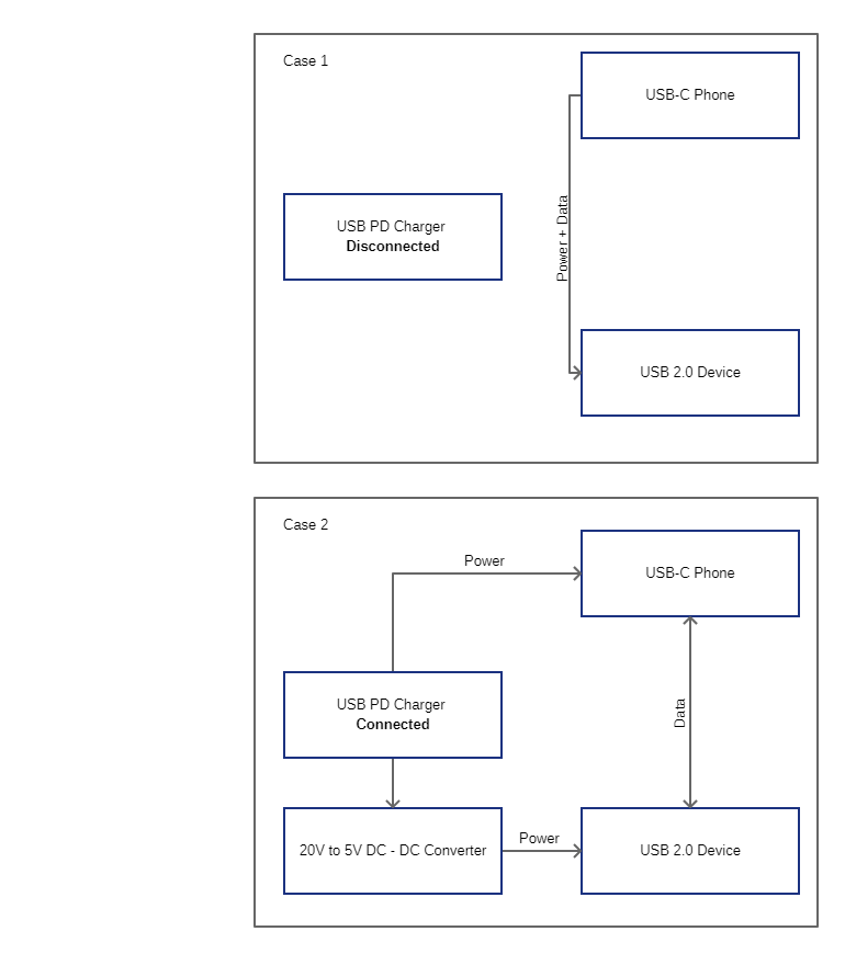
There would essentially be two conditions:

Condition/Case 1:

The device is not being charged but has a USB 2.0 device attached. In this case the USB 2.0 device would be powered and communicate with the phone directly.


Condition/Case 2:

In this case a USB Power Delivery Charger is connected to charge the phone.

When the charger is connected, the phone still needs to be able to access the USB 2.0 device, we can power the USB 2.0 device using a DC-DC converter to drop the incoming voltage to 5V.


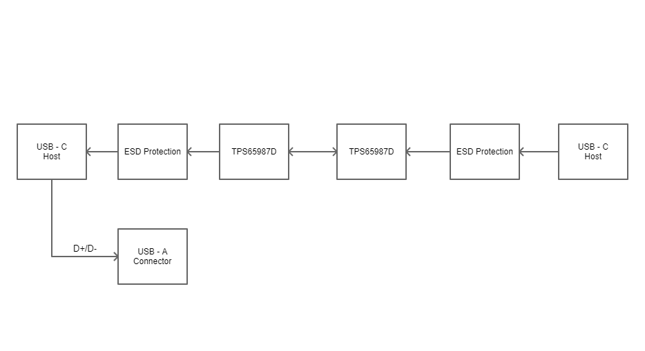
My query is which IC is suitable for this?


The most promising option that I found was the evaluation board TIDA-03027. What I would like to know is if this is the best option or if there is a simpler option available considering my requirement.


  • Hi Emil,

    From the PD controller perspective, I would recommend using the TPS65987D as it is our latest released single port PD3.0 controller. You could use a similar data architechture as on TIDA-03027. However, if you have questions specific to the data interface, I can ensure the proper device expert responds to your follow up questions.

    Thank you,
    Eric

  • Hi Eric,

    Thank you for getting back. So the function block would be something like below (without the voltage regulators)?

  • Hi Emil,

    I think the ESD protection should be between the TPS65987D and the Type-C Connector. I would swap the ESD protection block and TPS65987D block in your diagram, the rest looks OK to me.

    Thank you,
    Eric

  • Hi Eric,

    Thank you. Let me look into this and get back if I have any queries.

  • Hi Eric,

    In the setup, I will be using two TPS65987D, would there be a need for flash the firmware on both the controllers or just the one connecting to the phone?

    Additionally, in Case 2 of my original post would the controller automatically make the Phone act as the source to draw the power required for the USB 2.0 device?
    TPS65987D

  • Hi Emil,

    Both TPS65987Ds would need to receive firmware from an external SPI Flash chip.

    In case 2 it looks like the phone would be a sink as it appears to be charging from your device. If there is no external power on your device, the TPS65987D would automatically become the Sink and the phone would be sourcing power. When you need to charge the phone, and the TPS65987D is configured to become the source, the phone can be charged from your device.

    Thanks,
    Eric

  • I think I understood what you meant.

    Assuming the following, I have a few other queries.

    T1 - TPS65987D connected to connector on phone side

    T2 - TPS65987D connected to connector on charger side

    1. I am planning on connecting T1 to the FTDI via the SPI pins and I2C2 and T2 to the FTDI pins via the SPI pins (with a jumper for SS pin, making it easy to switch between controllers when programming) and I2C2. Would this be fine?

    2. Does it matter between T1 & T2, which is master?

    3. For T1. In the configuration tool, I see an option for i2c master configuration in which I can configure the salve address. However, I am not seeing an option that mentions that it will communicate with T2 to negotiate the power requirements from the Charger automatically. Is this default behavior? or have I missed something?

    E.g. T1 Configuration - To connect to Slave & act as master

    E.g. T2 Configuration - To behave as slave


  • Hi Emil,

    1. This should be ok from the PD controller perspective. As long as you are able to distinguish which Flash chip you are trying to program via SPI. 

    2. I'm not sure what you mean by master. If you are asking about I2C Master or Slave role, the TPS65987D would both be the I2C Slave and be controlled by an I2C master external to the PD controller.

    3. The I2C master is intended for controlling external circuitry. It is not intended to use this feature to have two TPS65987Ds communicating with one another. Here is an app note discussing the I2C master in TPS65987D: http://www.ti.com/lit/an/slvae18/slvae18.pdf

    Thank you,
    Eric

  • Hi  Eric,

    3. There seems to have been a misunderstanding in the interfacing as I thought the  two TPS65987D could  communicate with each other thereby avoiding the need for an external microcontroller as shown in TIDA-03027 using the TPS65983. I had mentioned this in the flowchart in my second posting.

    Would there be an alternative that can be used which does not  have a BGA padding that I can use?

  • Hi Emil,

    Neither the TPS65983B or TPS65987D have the ability to communicate with other PD Controller chips. The TPS65983B has a basic UART connection where one SPI Flash can be used to bootup two TPS65983Bs, there is no further communication. 

    There will need to be an external micocontroller in your system for either TPS65983B or TPS65987D. I would suggest using TPS65987D since it has the latest PD3.0 features.

    Thanks,
    Eric

  • I am clear on why the TPS65987D is a good fit.

    Could you please help me out with the controller used in the TIDA-03027 evaluation module as I cannot seem to find it in the Schematic diagram.

  • Hi Emil,

    The TIDA-03027 does not have a controller. The configurations on the PD controllers is enough to met the requirements of that design without requiring a controller.

    Thanks,
    Eric