This thread has been locked.

If you have a related question, please click the "Ask a related question" button in the top right corner. The newly created question will be automatically linked to this question.

PMP7499: UCC2897A the turn-on delay time

Part Number: PMP7499
Other Parts Discussed in Thread: TPS2379, , TPS23881, UCC2897A

Hi

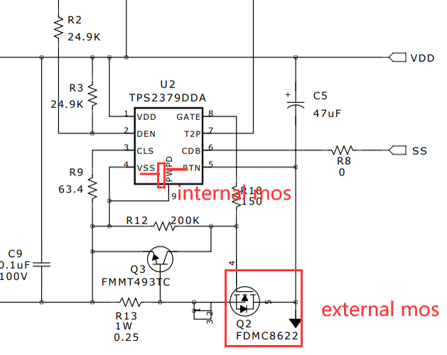
1,  I want to know, weather the PMP7499 reference design truely support a 12V@5A(60W) application ?  I mean, under 60W load, the internal and external MOSFET may flow 1.1A (at 57V voltage) continuously.  The TPS2379 will not shutdown due to thermal?

2,  And there is also a question.

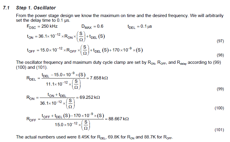
According from slua535, its assumed turn-on delay time is 0.1us;  and the typical fsw is 250kHz. Therefore, the RON could be 69.8k, and ROFF could be 88.7k.

But in PMP7499, RON is R30=80.6k and ROFF is R31=61.9k.

Where are the two value caculated from?

What is the turn-on delay time in PMP7499 reference design?

And RON=69.8k, ROFF=88.7k also will be ok for this reference design?

http://www.ti.com/cn/lit/df/slvrb55/slvrb55.pdf

Thank you.

  • Kingson,

    1.  Yes, this design can supply a 60W load.  The input current will divide between the internal hot swap FET of the TPS2379 and the external FET Q2 + R13.  The TPS2379 hot swap FET has a nominal Rdson of 0.42 ohms.  Q2 has a nominal Rdson of 56 milliohms plus R13 = 0.25 ohms.  The input current will divide between 0.42 ohms and 0.306 ohms.  Although the TPS2379 will operate satisfactorily, it is not compliant with the new IEEE802.3bt PoE specification.  I would recommend looking at the TPS2373-4 PD controller to replace the TPS2379.  It is fully compliant with the new PoE specification and does not require an external FET to supply 60W.

    2.  The delay time is base on the time needed for the primary FET to complete its zero voltage transition.  Since the transition time depends on parasitic components it is hard to calculate.  RDEL = 6.98k was based on measurements of the circuit waveforms and results in a delay time of 92.5nsec.  This design requires a maximum operating duty cycle of 68%.  I set the duty cycle clamp to 75% to account for circuit tolerances, switching times, and transients.  Since this design was done there have been some slight adjustments to the oscillator equations in the datasheet/app note.  Based on the new equations I calculate Ron = 85.6k and Roff = 61.5k for 250kHz, 75% max duty cycle and 92.5nsec delay.  Using 80.6k for Ron yields 74% max duty cycle and 257kHz, which will be ok.  To get closer to the nominal values or 75% and 250kHz use Ron = 84.5k or 86.6k.

    Thanks,

    David

  • Hi David

    For TI's PoE ICs, compliant with the new IEEE802.3bt means that, these ICs also compliant with other semi-manufacturer's PoE ICs ?

    Is TPS23881 PSE support ON-SEMI's PD NCP1083 which support the IEEE 802.3af and the 802.3at Standard ?

  • Kingson,

    If the other ICs are compliant with the bt/at/af spec then they should work with TI PoE ICs.

    I can't speak for this specific IC, but the TPS23881 supports Type 1 (af), Type 2 (at) and Type 3/4 (bt) power levels.  The bt spec incorporates all power levels and is backwards compatible.

    Thanks,

    David

  • Hi David

    I'm very interested in PMP7499, and I want to copy this reference design for our application circuit.

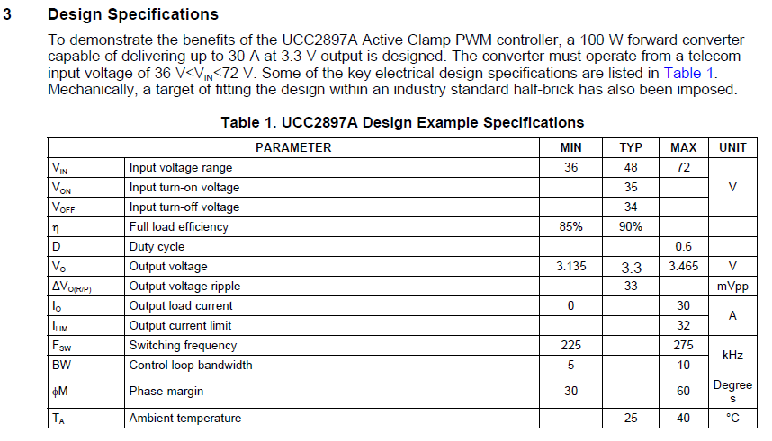
    But I didn't get any design requirements of PMP7499, such as the following table in slua535.

    1, Could you share the design requirements of PMP7499 with me if you have ?  For example, the " sluc662  UCC2897A Controller Setup Tool (Excel) " of PMP7499.

    2, By the way, there are no design requirements for most TI reference design I have seen, it is not friendly. Could you help me to push this question ? 

    Because I don't know why the capatance or resistance come from if there are no design requirements.

    Thank you.


    http://www.ti.com/lit/an/slua535/slua535.pdf

  • Hi David

    1, Assumed that, Fsw = 250kHz, Dmax = 75%, tdel = 92.5ns=92.5*10^(-9)(s)

    Due to Tsw = 1/Fsw = ton + toff = 1/250kHz = 4000 * 10^(-9)(s), and Dmax = ton / ( ton + toff ) = 0.75,

    So ton = 3000 * 10^(-9)(s), and toff = 1000 * 10^(-9)(s)

    Why did you select the tdel = 92.5ns ? what is this parameter associated with ?

    2, tdel = 11.1 * 10^(-12) * Rdel (s/ohm) + 15.0 * 10^(-9) (s)

        ton = 36.1 * 10^(-12) * Ron (s/ohm) - tdel (s)

        toff = 15.0 * 10^(-12) * Roff (s/ohm) + tdel (s) + 170.0 * 10^(-9) (s)

    So Rdel = ( tdel (s) -15.0 * 10^(-9) (s) ) / 11.1 * 10^(-12) (s/ohm) = ( 92.5 -15.0 ) * 10^(-9) (s) / 11.1 * 10^(-12) (s/ohm) = 6.98 kohm

         Ron  = ( ton (s) + tdel (s) ) / 36.1 * 10^(-12) (s/ohm) = ( 3000 + 92.5 ) * 10^(-9) (s) / 36.1 * 10^(-12) (s/ohm) = 85.6 kohm

         Roff  = ( toff (s) - tdel (s) - 170.0 * 10^(-9) (s) ) / 15.0  * 10^(-12) (s/ohm) =( 1000 - 92.5 -170.0 ) * 10^(-9) (s) / 15.0  * 10^(-12) (s/ohm) = 49.17 kohm

    Please note that, the Roff value I calculated is 49.17 kohm, which is not the Roff = 61.5k you give me. why?

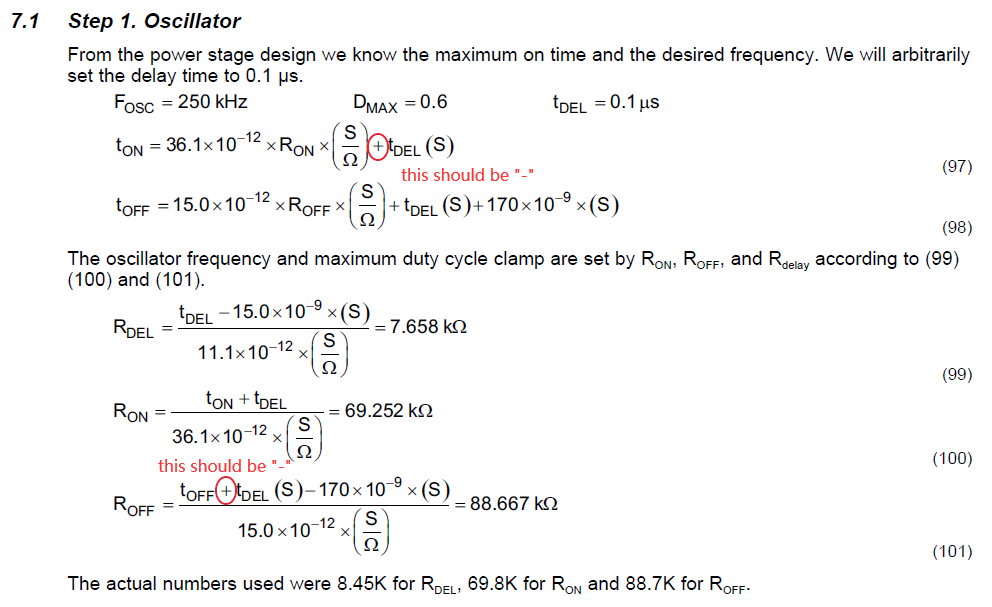
    3, The above formula come from slua535 and ucc2897a datasheet. It seems that, there are two symbol error in slua535 formula (97) and (101) ?

  • Kingson,

    From the previous post, I do not have a table of the design requirements for PMP7499.  The test reports contain measurements of these parameters.  I will pass along your request to add a requirements table to the test reports.

    I was still using the wrong equation for Roff.  I also get 49.17k when I use the equations in the current datasheet, 6.98k for Rdel, 75% max duty cycle, and 250kHz switching frequency.  I calculate Ron = 85.6k.

    I sent the information on equations 97 and 101 to applications support for the UCC2897A.

    Thanks,

    David

  • Hi David

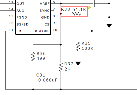
    What is the purpose of R33=51.1k? and it is optical? because there is no this resistor in PMP6547 reference design.

  • Hi,

    The R33/R20 divider adds a dc bias to the current sense signal.  This allows the use of a smaller value current sense resistor, reducing the power dissipation in it.

    Thanks,

    David