This thread has been locked.

If you have a related question, please click the "Ask a related question" button in the top right corner. The newly created question will be automatically linked to this question.

Compiler/CC2640R2F: SaBLE-x-R2 debugg problems

Part Number: CC2640R2F

Tool/software: TI C/C++ Compiler

Hello,

I am using the SaBLE-x-R2 development board i have encountered a problem. Namely, I would like to run the code using the step by stem mode in the Debugg view. I can't use the Terminal on Code Composer studio becouse my development board is a little specific. So I have to use the RealTerm serial monitor. The problem occurs when I am running the code in the debugg mode and try in the same time to connect the board on RealTerm. When a connection is established, I get two errors in the debugger:

Cortex_M3_0: Error: (Error -1170 @ 0x0) Unable to access the DAP. Reset the device, and retry the operation. If error persists, confirm configuration, power-cycle the board, and/or try more reliable JTAG settings (e.g. lower TCLK). (Emulation package 8.0.27.9)


Cortex_M3_0: Trouble Halting Target CPU: (Error -2064 @ 0x0) Unable to read device status. Reset the device, and retry the operation. If error persists, confirm configuration, power-cycle the board, and/or try more reliable JTAG settings (e.g. lower TCLK). (Emulation package 8.0.27.9)

With these errors I am being forcefully stepped out the debugg mode. What sould I do? How can I be in the debugg mode(I'm using the XDS110) and in the same time see my serial output from my board on a serial monitor? I need that to connect the board to another board via ble5.

  • Alen,

    This sounds to me like signal integrity issues, can you post your schematic for me to have a look at it. Also I recommend getting an oscilloscope to confirm that the JTAG line signals are nice rail-rail signals that contains no "extra noise" when you enable UART.

    Regards,
    /TA
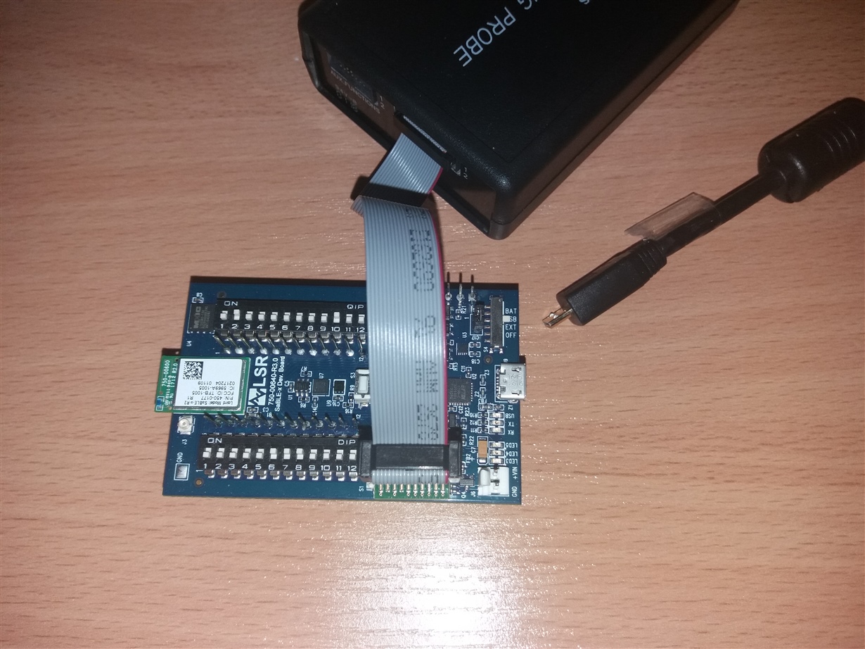
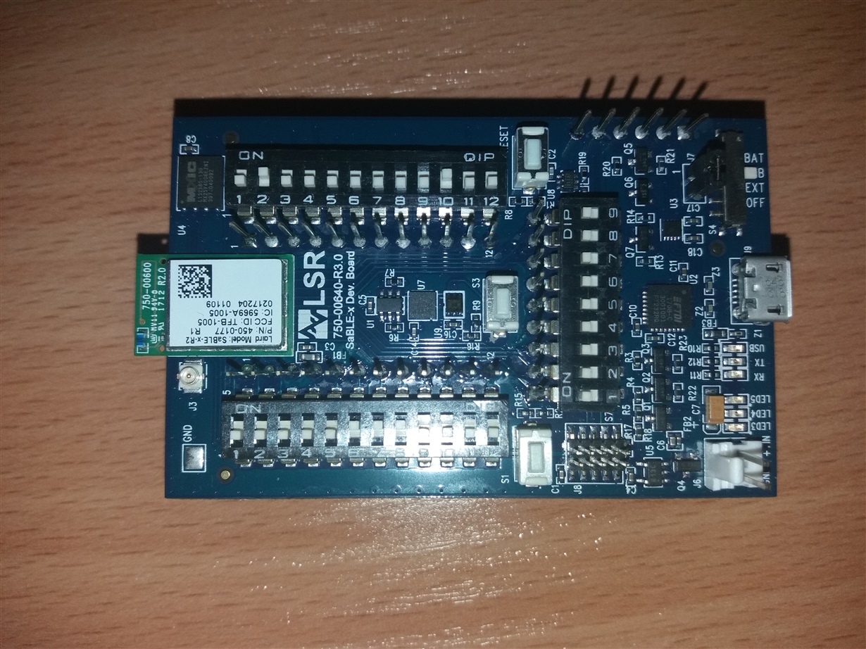
  • Well, i have no special schematics. In the pictures below you can see the connection configuration of the XDS110 and the usb to the PC. The other picture represents the switch setup for the board bootload.

    Regards Alen  

  • I should also mention that in my port map I have: COM6 USB Serial Port , COM4 XDS110 Class Application(User UART, COM5 XDS110 Class Auxiliary Data Port. When I connect the SaBLE to Realterm, I use the COM6 port. And then I get the error. But when I use the COM4, I do not get a error but i have no output on Realterm.

    Regards Alen
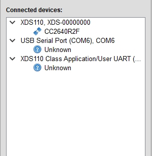
  • If you use Flash Programmer 2, can it recognize your CC2640R2F?
  • I have installed the flash programmer 2, and I thing due to the ooutput on the picture, that it can see the development board. I should also mention that as you can see the XDS110 is also visible and that I have not connected the dev. board with the XDS110 while taking this screen shot.

    Regards Alen

  • I couldn't understand your reply. Can you reply if Flash Programmer 2 can recognize your CC2640R2F?
  • I'm so sorry I thought I have uploaded the screen shot.

  • CC2640R2F doesn’t show on XDS110 tree view which means There’s something wrong on JTAG connection. I suggest you to check JTAG connection first.
  • The JTAG wasn't connected. Now it is, and it is shown.

  • It looks good now and you should be able to use CCS to do trace/debug examples now.
  • Greetings,

    unfortunately i can not. When I am in the debug mode, i open a CCS terminal, and choose COM4, nothing happens. And with the other COM-s 5 and 6 also have no output. My dev board needs to use the RTS/CTS to control reset. RealTerm allows me to clear RTS and CTS.

    Regards,

    Alen

  • Are you sure your TX/RX pin assignment in board file matches your schematics?
  • Here are my board files: 

    /*
     *  ====================== SABLEXR2_DEV_BOARD.c ===================================
     *  This file is responsible for setting up the board specific items for the
     *  SaBLE-x-R2 module on the SaBLE-x Dev Board.
     */
    
    #include <xdc/std.h>
    #include <xdc/runtime/System.h>
    #include <ti/sysbios/family/arm/m3/Hwi.h>
    
    #include <ti/devices/cc26x0r2/driverlib/ioc.h>
    #include <ti/devices/cc26x0r2/driverlib/udma.h>
    #include <ti/devices/cc26x0r2/inc/hw_ints.h>
    #include <ti/devices/cc26x0r2/inc/hw_memmap.h>
    
    #include "SABLEXR2_DEV_BOARD.h"
    
    /*
     *  =============================== Display ===============================
     */
    #include <ti/display/Display.h>
    #include <ti/display/DisplayUart.h>
    
    #ifndef BOARD_DISPLAY_UART_STRBUF_SIZE
    #define BOARD_DISPLAY_UART_STRBUF_SIZE    128
    #endif
    
    DisplayUart_Object     displayUartObject;
    
    static char uartStringBuf[BOARD_DISPLAY_UART_STRBUF_SIZE];
    
    const DisplayUart_HWAttrs displayUartHWAttrs = {
        .uartIdx      = CC2640R2_SABLEXR2_UART0,
        .baudRate     = 115200,
        .mutexTimeout = (unsigned int)(-1),
        .strBuf       = uartStringBuf,
        .strBufLen    = BOARD_DISPLAY_UART_STRBUF_SIZE,
    };
    
    #ifndef BOARD_DISPLAY_USE_UART
    #define BOARD_DISPLAY_USE_UART 1
    #endif
    #ifndef BOARD_DISPLAY_USE_UART_ANSI
    #define BOARD_DISPLAY_USE_UART_ANSI 0
    #endif
    #ifndef BOARD_DISPLAY_USE_LCD
    #define BOARD_DISPLAY_USE_LCD 0
    #endif
    
    /*
     * This #if/#else is needed to workaround a problem with the
     * IAR compiler. The IAR compiler doesn't like the empty array
     * initialization. (IAR Error[Pe1345])
     */
    #if (BOARD_DISPLAY_USE_UART)
    
    const Display_Config Display_config[] = {
    #if (BOARD_DISPLAY_USE_UART)
        {
    #  if (BOARD_DISPLAY_USE_UART_ANSI)
            .fxnTablePtr = &DisplayUartAnsi_fxnTable,
    #  else /* Default to minimal UART with no cursor placement */
            .fxnTablePtr = &DisplayUartMin_fxnTable,
    #  endif
            .object      = &displayUartObject,
            .hwAttrs     = &displayUartHWAttrs,
        },
    #endif
    };
    
    const uint_least8_t Display_count = sizeof(Display_config) / sizeof(Display_Config);
    
    #else
    
    const Display_Config *Display_config = NULL;
    const uint_least8_t Display_count = 0;
    
    #endif /* (BOARD_DISPLAY_USE_UART || BOARD_DISPLAY_USE_LCD) */
    
    /*
     *  =============================== Power ===============================
     */
    #include <ti/drivers/Power.h>
    #include <ti/drivers/power/PowerCC26XX.h>
    
    const PowerCC26XX_Config PowerCC26XX_config = {
        .policyInitFxn      = NULL,
        .policyFxn          = &PowerCC26XX_standbyPolicy,
        .calibrateFxn       = &PowerCC26XX_calibrate,
        .enablePolicy       = TRUE,
    #ifdef USE_RCOSC    
        .calibrateRCOSC_LF  = TRUE,
    #else
        .calibrateRCOSC_LF  = FALSE,
    #endif
        .calibrateRCOSC_HF  = TRUE,
    };
    
    /*
     *  =============================== Crypto ===============================
     */
    #include <ti/drivers/crypto/CryptoCC26XX.h>
    
    CryptoCC26XX_Object cryptoCC26XXObjects[CC2640R2_SABLEXR2_CRYPTOCOUNT];
    
    const CryptoCC26XX_HWAttrs cryptoCC26XXHWAttrs[CC2640R2_SABLEXR2_CRYPTOCOUNT] = {
        {
            .baseAddr       = CRYPTO_BASE,
            .powerMngrId    = PowerCC26XX_PERIPH_CRYPTO,
            .intNum         = INT_CRYPTO_RESULT_AVAIL_IRQ,
            .intPriority    = ~0,
        }
    };
    
    const CryptoCC26XX_Config CryptoCC26XX_config[CC2640R2_SABLEXR2_CRYPTOCOUNT] = {
        {
             .object  = &cryptoCC26XXObjects[CC2640R2_SABLEXR2_CRYPTO0],
             .hwAttrs = &cryptoCC26XXHWAttrs[CC2640R2_SABLEXR2_CRYPTO0]
        },
    };
    
    /*
     *  =============================== PIN ===============================
     */
    #include <ti/drivers/PIN.h>
    #include <ti/drivers/pin/PINCC26XX.h>
    
    const PIN_Config BoardGpioInitTable[] = {
    
        Board_GLED       | PIN_GPIO_OUTPUT_EN | PIN_GPIO_HIGH   | PIN_PUSHPULL | PIN_DRVSTR_MAX,    /* LED initially off             */
        Board_BLED       | PIN_GPIO_OUTPUT_EN | PIN_GPIO_HIGH   | PIN_PUSHPULL | PIN_DRVSTR_MAX,    /* LED initially off             */
        Board_RLED       | PIN_GPIO_OUTPUT_EN | PIN_GPIO_HIGH   | PIN_PUSHPULL | PIN_DRVSTR_MAX,    /* LED initially off             */
        Board_KEY1       | PIN_INPUT_EN  | PIN_PULLUP | PIN_HYSTERESIS,                             /* Button is active low          */
        Board_KEY2       | PIN_INPUT_EN  | PIN_PULLUP | PIN_HYSTERESIS,                             /* Button is active low          */
        Board_SPI0_CSN   | PIN_GPIO_OUTPUT_EN | PIN_GPIO_HIGH   | PIN_PUSHPULL,                     /* CS pin at inactive level */
    
        Board_UART_TX    | PIN_GPIO_OUTPUT_DIS | PIN_INPUT_EN   | PIN_PULLUP,                       /* UART TX pin at inactive level */
        Board_UART_RX    | PIN_GPIO_OUTPUT_DIS | PIN_INPUT_EN   | PIN_PULLUP,                       /* UART RX pin at inactive level */
        PIN_TERMINATE                                                                               /* Terminate list                */
    };
    
    const PINCC26XX_HWAttrs PINCC26XX_hwAttrs = {
        .intPriority = ~0,
        .swiPriority = 0
    };
    
    /*
     *  =============================== RF Driver ===============================
     */
    #include <ti/drivers/rf/RF.h>
    
    /* For SDK v1.35.00 */
    /*
    const RFCC26XX_HWAttrs RFCC26XX_hwAttrs = {
        .hwiCpe0Priority = ~0,
        .hwiHwPriority   = ~0,
        .swiCpe0Priority =  5,
        .swiHwPriority   =  5,
    };
    */
    
    /* For SDK v2.20.00 */
    const RFCC26XX_HWAttrs RFCC26XX_hwAttrs = {
        .hwiCpe0Priority = ~0,
        .hwiHwPriority   = ~0,
        .swiCpe0Priority =  5,
        .swiHwPriority   =  5,
    };


    /*
     *  =============================== UART ===============================
     */
    #include <ti/drivers/UART.h>
    #include <ti/drivers/uart/UARTCC26XX.h>
    
    UARTCC26XX_Object uartCC26XXObjects[CC2640R2_SABLEXR2_UARTCOUNT];
    
    const UARTCC26XX_HWAttrsV2 uartCC26XXHWAttrs[CC2640R2_SABLEXR2_UARTCOUNT] = {
        {
            .baseAddr       = UART0_BASE,
            .powerMngrId    = PowerCC26XX_PERIPH_UART0,
            .intNum         = INT_UART0_COMB,
            .intPriority    = ~0,
            .swiPriority    = 0,
            .txPin          = Board_UART_TX,
            .rxPin          = Board_UART_RX,
            .ctsPin         = PIN_UNASSIGNED,
            .rtsPin         = PIN_UNASSIGNED
        }
    };
    
    const UART_Config UART_config[CC2640R2_SABLEXR2_UARTCOUNT] = {
        {
            .fxnTablePtr = &UARTCC26XX_fxnTable,
            .object      = &uartCC26XXObjects[CC2640R2_SABLEXR2_UART0],
            .hwAttrs     = &uartCC26XXHWAttrs[CC2640R2_SABLEXR2_UART0]
        },
    };
    
    const uint_least8_t UART_count = CC2640R2_SABLEXR2_UARTCOUNT;
    
    /*
     *  =============================== UDMA ===============================
     */
    #include <ti/drivers/dma/UDMACC26XX.h>
    
    UDMACC26XX_Object udmaObjects[CC2640R2_SABLEXR2_UDMACOUNT];
    
    const UDMACC26XX_HWAttrs udmaHWAttrs[CC2640R2_SABLEXR2_UDMACOUNT] = {
        {
            .baseAddr    = UDMA0_BASE,
            .powerMngrId = PowerCC26XX_PERIPH_UDMA,
            .intNum      = INT_DMA_ERR,
            .intPriority = ~0
        }
    };
    
    const UDMACC26XX_Config UDMACC26XX_config[CC2640R2_SABLEXR2_UDMACOUNT] = {
        {
             .object  = &udmaObjects[CC2640R2_SABLEXR2_UDMA0],
             .hwAttrs = &udmaHWAttrs[CC2640R2_SABLEXR2_UDMA0]
        },
    };
    
    /*
     *  ======== CC2640R2_SABLEXR2_initGeneral ========
     */
    void CC2640R2_initGeneral(void)
    {
        Power_init();
    
        if (PIN_init(BoardGpioInitTable) != PIN_SUCCESS) {
            System_abort("Error with PIN_init\n");
        }
    }
    
    /*
     *  ========================= TRNG begin ====================================
     */
    #include <TRNGCC26XX.h>
    
    /* TRNG objects */
    TRNGCC26XX_Object trngCC26XXObjects[CC2640R2_SABLEXR2_TRNGCOUNT];
    
    /* TRNG configuration structure, describing which pins are to be used */
    const TRNGCC26XX_HWAttrs TRNGCC26XXHWAttrs[CC2640R2_SABLEXR2_TRNGCOUNT] = {
        {
            .powerMngrId    = PowerCC26XX_PERIPH_TRNG,
        }
    };
    
    /* TRNG configuration structure */
    const TRNGCC26XX_Config TRNGCC26XX_config[] = {
        {
             .object  = &trngCC26XXObjects[0],
             .hwAttrs = &TRNGCC26XXHWAttrs[0]
        },
        {NULL, NULL}
    };
    
    /*
     *  ========================= TRNG end ====================================
     */
    
    /*
     *  =============================== SPI DMA ===============================
     */
    #include <ti/drivers/SPI.h>
    #include <ti/drivers/spi/SPICC26XXDMA.h>
    
    SPICC26XXDMA_Object spiCC26XXDMAObjects[CC2640R2_SABLEXR2_SPICOUNT];
    
    const SPICC26XXDMA_HWAttrsV1 spiCC26XXDMAHWAttrs[CC2640R2_SABLEXR2_SPICOUNT] = {
        {
            .baseAddr           = SSI0_BASE,
            .intNum             = INT_SSI0_COMB,
            .intPriority        = ~0,
            .swiPriority        = 0,
            .powerMngrId        = PowerCC26XX_PERIPH_SSI0,
            .defaultTxBufValue  = 0,
            .rxChannelBitMask   = 1<<UDMA_CHAN_SSI0_RX,
            .txChannelBitMask   = 1<<UDMA_CHAN_SSI0_TX,
            .mosiPin            = Board_SPI0_MOSI,
            .misoPin            = Board_SPI0_MISO,
            .clkPin             = Board_SPI0_CLK,
            .csnPin             = Board_SPI0_CSN
        }
    };
    
    const SPI_Config SPI_config[CC2640R2_SABLEXR2_SPICOUNT] = {
        {
             .fxnTablePtr = &SPICC26XXDMA_fxnTable,
             .object      = &spiCC26XXDMAObjects[CC2640R2_SABLEXR2_SPI0],
             .hwAttrs     = &spiCC26XXDMAHWAttrs[CC2640R2_SABLEXR2_SPI0]
        }
    };
    
    const uint_least8_t SPI_count = CC2640R2_SABLEXR2_SPICOUNT;
    
    /*
     *  =============================== I2C ===============================
    */
    #include <ti/drivers/I2C.h>
    #include <ti/drivers/i2c/I2CCC26XX.h>
    
    I2CCC26XX_Object i2cCC26xxObjects[CC2640R2_SABLEXR2_I2CCOUNT];
    
    const I2CCC26XX_HWAttrsV1 i2cCC26xxHWAttrs[CC2640R2_SABLEXR2_I2CCOUNT] = {
        {
            .baseAddr    = I2C0_BASE,
            .powerMngrId = PowerCC26XX_PERIPH_I2C0,
            .intNum      = INT_I2C_IRQ,
            .intPriority = ~0,
            .swiPriority = 0,
            .sdaPin      = Board_I2C0_SDA0,
            .sclPin      = Board_I2C0_SCL0,
        }
    };
    
    const I2C_Config I2C_config[CC2640R2_SABLEXR2_I2CCOUNT] = {
        {
            .fxnTablePtr = &I2CCC26XX_fxnTable,
            .object      = &i2cCC26xxObjects[CC2640R2_SABLEXR2_I2C0],
            .hwAttrs     = &i2cCC26xxHWAttrs[CC2640R2_SABLEXR2_I2C0]
        },
    };
    
    const uint_least8_t I2C_count = CC2640R2_SABLEXR2_I2CCOUNT;
    
    #ifndef __SABLEXR2_DEV_BOARD_H__
    #define __SABLEXR2_DEV_BOARD_H__
    
    #ifdef __cplusplus
    extern "C" {
    #endif
    
    /* Includes */
    #include <ti/drivers/PIN.h>
    #include <ti/devices/cc26x0r2/driverlib/ioc.h>
    
    /* Externs */
    extern const PIN_Config BoardGpioInitTable[];
    
    /* Defines */
    #ifndef SABLEXR2_DEV_BOARD
      #define SABLEXR2_DEV_BOARD
    #endif /* SABLEXR2_DEV_BOARD */
    
    /** ============================================================================
     *  Symbol by generic Board.c to include the correct kit specific Board.c
     *  ==========================================================================*/
    #define CC2650EM_5XD
    
    /* Mapping of pins to board signals using general board aliases
     *      <board signal alias>                  <pin mapping>
     */
    //LEDs
    #define Board_LED_ON                        0 /* LEDs on SaBLE-x EM board LEDs are active low */
    #define Board_LED_OFF                       1
    #define Board_GLED                          IOID_14
    #define Board_BLED                          IOID_8
    #define Board_RLED                          IOID_4
    // Button Board
    #define Board_KEY1                          IOID_7
    #define Board_KEY2                          IOID_9
    // Other button definitions for code compatibility 
    #define Board_PIN_BUTTON0                   Board_KEY1
    #define Board_PIN_BUTTON1                   Board_KEY2
    #define Board_BTN1                          Board_KEY1
    #define Board_BTN2                          Board_KEY2
    // UART Board
    #define Board_UART_RX                       IOID_1
    #define Board_UART_TX                       IOID_0
    #define Board_UART_CTS                      PIN_UNASSIGNED
    #define Board_UART_RTS                      PIN_UNASSIGNED
    // SPI Board
    #define Board_SPI0_MISO                     IOID_12
    #define Board_SPI0_MOSI                     IOID_11
    #define Board_SPI0_CLK                      IOID_13
    #define Board_SPI0_CSN                      IOID_10
    #define Board_SPI1_MISO                     PIN_UNASSIGNED
    #define Board_SPI1_MOSI                     PIN_UNASSIGNED
    #define Board_SPI1_CLK                      PIN_UNASSIGNED
    #define Board_SPI1_CSN                      PIN_UNASSIGNED
    //I2C Board
    //todo-btm
    #define Board_I2C0_SDA0						IOID_2
    #define Board_I2C0_SCL0						IOID_3
    
    #define Board_PIN_ON  1
    #define Board_PIN_OFF 0
    
    /*!
     *  @brief  Initialize the general board specific settings
     *
     *  This function initializes the general board specific settings.
     */
    void CC2640R2_initGeneral(void);
    
    /*!
     *  @def    CC2640R2_SABLEXR2_CryptoName
     *  @brief  Enum of Crypto names
     */
    typedef enum CC2640R2_SABLEXR2_CryptoName {
        CC2640R2_SABLEXR2_CRYPTO0 = 0,
    
        CC2640R2_SABLEXR2_CRYPTOCOUNT
    } CC2640R2_SABLEXR2_CryptoName;
    
    /*!
     *  @def    CC2640R2_SABLEXR2_UARTName
     *  @brief  Enum of UARTs
     */
    typedef enum CC2640R2_SABLEXR2_UARTName {
        CC2640R2_SABLEXR2_UART0 = 0,
    
        CC2640R2_SABLEXR2_UARTCOUNT
    } CC2640R2_SABLEXR2_UARTName;
    
    /*!
     *  @def    CC2640R2_SABLEXR2_UDMAName
     *  @brief  Enum of DMA buffers
     */
    typedef enum CC2640R2_SABLEXR2_UDMAName {
        CC2640R2_SABLEXR2_UDMA0 = 0,
    
        CC2640R2_SABLEXR2_UDMACOUNT
    } CC2640R2_SABLEXR2_UDMAName;
    
    /*!
     *  @def    CC2640R2_SABLEXR2_TRNGName
     *  @brief  Enum of TRNG names on the board
     */
    typedef enum CC2640R2_SABLEXR2_TRNGName {
        CC2640R2_SABLEXR2_TRNG0 = 0,
        CC2640R2_SABLEXR2_TRNGCOUNT
    } CC2640R2_SABLEXR2_TRNGName;
    
    /*!
     *  @def    CC2640R2_SABLEXR2_I2CName
     *  @brief  Enum of I2C interfaces
     */
    typedef enum CC2640R2_SABLEXR2_I2CName {
        CC2640R2_SABLEXR2_I2C0 = 0,
    
        CC2640R2_SABLEXR2_I2CCOUNT
    } CC2640R2_SABLEXR2_I2CName;
    
    /*!
     *  @def    CC2640R2_SABLEXR2_SPIName
     *  @brief  Enum of SPI interfaces
     */
    typedef enum CC2640R2_SABLEXR2_SPIName {
        CC2640R2_SABLEXR2_SPI0 = 0,
    
        CC2640R2_SABLEXR2_SPICOUNT
    } CC2640R2_SABLEXR2_SPIName;
    
    #ifdef __cplusplus
    }
    #endif
    
    #endif /* __SABLEXR2_DEV_BOARD_H__ */
    

  • Do you have a CC2640R2F LaunchPAD? I do not have access to the module HW that you have so its hard for us to replicate it.

    I do not know why there are 3 UART ports, because we typically only have two.

    Regards,
    /TA
  • Hello,

    no I do not have your Lounchpad, I have the LSR development board with your (TI) processor. I think I have solved my problem. Before entering the debugg mode, one should have established a connection with the RealTerm serial monitor. One should connect to the port designated to the board alone( USB serial port COM6), not the port designated XDS110 class .../User UART(COM4). And when you have output on RealTerm you go and click debugg. It wont crash any more. So not after clicking on debugg but before it, connect the board with the serial monitor. And for the debugging itself of the code I think that it is a mess, becouse it is for an unknown reason not possible.

    Regards Alen.