This thread has been locked.

If you have a related question, please click the "Ask a related question" button in the top right corner. The newly created question will be automatically linked to this question.

CC2652R: In Circuit programming of custom board

Part Number: CC2652R
Other Parts Discussed in Thread: UNIFLASH, SYSBIOS,

Having issues with programming our custom board based on the CC2652 via USB and the boot loader.  UniFlash doesn't seem to support the USB interface.  The latest version of SmartRF Flash Programmer 2 now supports the CC2652, and it works to query the board and read from it, but it fails when attempting to program the flash.  I don't think it is the interface or my board because I can successfully read the entire Flash without errors.

Initially, I checked "erase", "program", and "verify" before hitting start, but it failed every time.

Doing the steps one at a time, I was able to erase flash sectors (but not bulk erase everything), and the verification would run, but of course the images didn't match.

After erasing, I attempted to program the entire program (at this point, just a LED blink test), but it failed.  So I thought I'd try a partial program...  I entered "0-10" in the "exclude sectors" -- and then it worked... Except it also locked the device (despite me NOT checking that option) and gave me a message about no further programming being possible.  And since it was only partially programmed, it's now a brick.

Before I brick another board, does anyone know:

A)  Why partial programming works, but complete programming fails?

B)  Why SmartRF Flash locked my board after programming -- and how I can keep that from happening again?

C). I have a button tied to DIO4 -- how do I set the board configuration to allow that button to re-activate the boot loader?

Thanks in advance for any advice.

   --Rhett

  • - Could you post screenshots on how you use Flash Programmer 2?
    - Do you actually use the bootloader?
    -. Which board do you use as a USB to UART interface?
    - Try mass erase on the bricked device (from the menu in the upper right corner)
    - The only thing that could brick the device is the settings in the CCFG section that is placed in the last flash page. If you have ticket the keep CCFG section you should not be able to brick the board.
    - For DIO4, see the ccfg.c file in your project, it's a bootloader section is this file.
  • - Could you post screenshots...

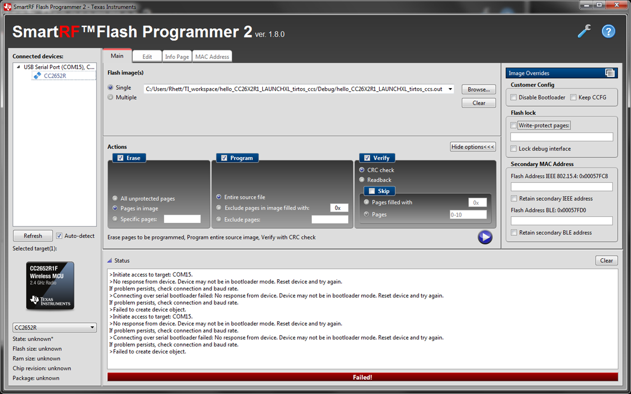
    See below... Not sure how helpful this is.  This is how I attempted to use it.  (Yes, I should have checked "keep CFG" and didn't.)  Of note, it failed to program like this, but later worked when I "excluded pages 0-10"... I didn't expect excluding a few pages to make any difference, and I still have no idea why that would work when "entire source file" failed.

    - Do you actually use the bootloader?

    Yes.  Custom board w/ USB interface.  Bootloader is had to live without.  ;-)

    -. Which board do you use as a USB to UART interface?

    Custom board.  Similar in many ways to a SensorTag, but with a USB connector.  Using a direct connection from PC to the board.  The board has a FT234XD-R USB Bridge chip that then connects to the CC2652R1F.

    - Try mass erase on the bricked device...

    >No response from device. Device may not be in bootloader mode. Reset device and try again.   (See above screenshot.)

    - The only thing that could brick the device is the settings in the CCFG...

    And, yes, I failed to do that.  By default, SmartRF Flash has both "Disable Bootloader" and "Keep CFG" unchecked.  While I was not foolish enough to check the "Disable Bootloader" box, I did not realize that NOT checking "Keep CFG" would amount to the same thing.

    - For DIO4, see the ccfg.c file in your project, it's a bootloader section is this file.

    Found it, thank you.  Not directly there... it just includes the default driverlib file for the device.

    Rather nasty that the default config file defaults to disabling the bootloader.  One would expect the defaults to not immediately lock out the device on the very first build/load...  I'd expect to have to change settings to lock down the device when I'm finally ready.  Immediate lockdown as default is something of a shock.  Apparently TI expects the first build/upload to be perfect.  Or expects one to know all the lockdown settings when they're just getting started with a new device and environment.  A simple warning (that could be disabled) about locking down the device *BEFORE* programming would be nice -- rather than a messages after it's too late.  (Obviously, SmartRF Flash Programmer knows to what it has done... it would be nice if it instead warned about what it was about to do...  With an option to disable that warning once you get to purposely locking down lots of boards.)

    Still, thanks for the advice.  The BOOTLOADER params weren't immediately obvious.  Would have taken a while to find them without your help.

    Thanks much,

       --Rhett

  • Normally it should not be required to think about the "disable bootloader", "keep CCFG" boxes since this is normally controlled by the CCFG file and the default CCFG section is setup to not disable anything.

    It's a bit hard to see from an out file, have you tried to generate a .hex file and see what you tried to set the ccfg section to?
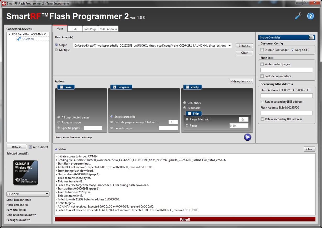
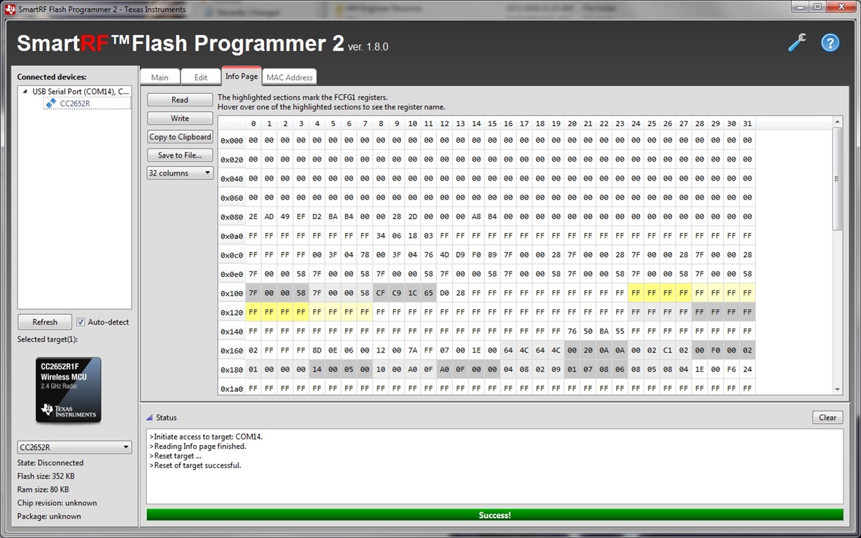
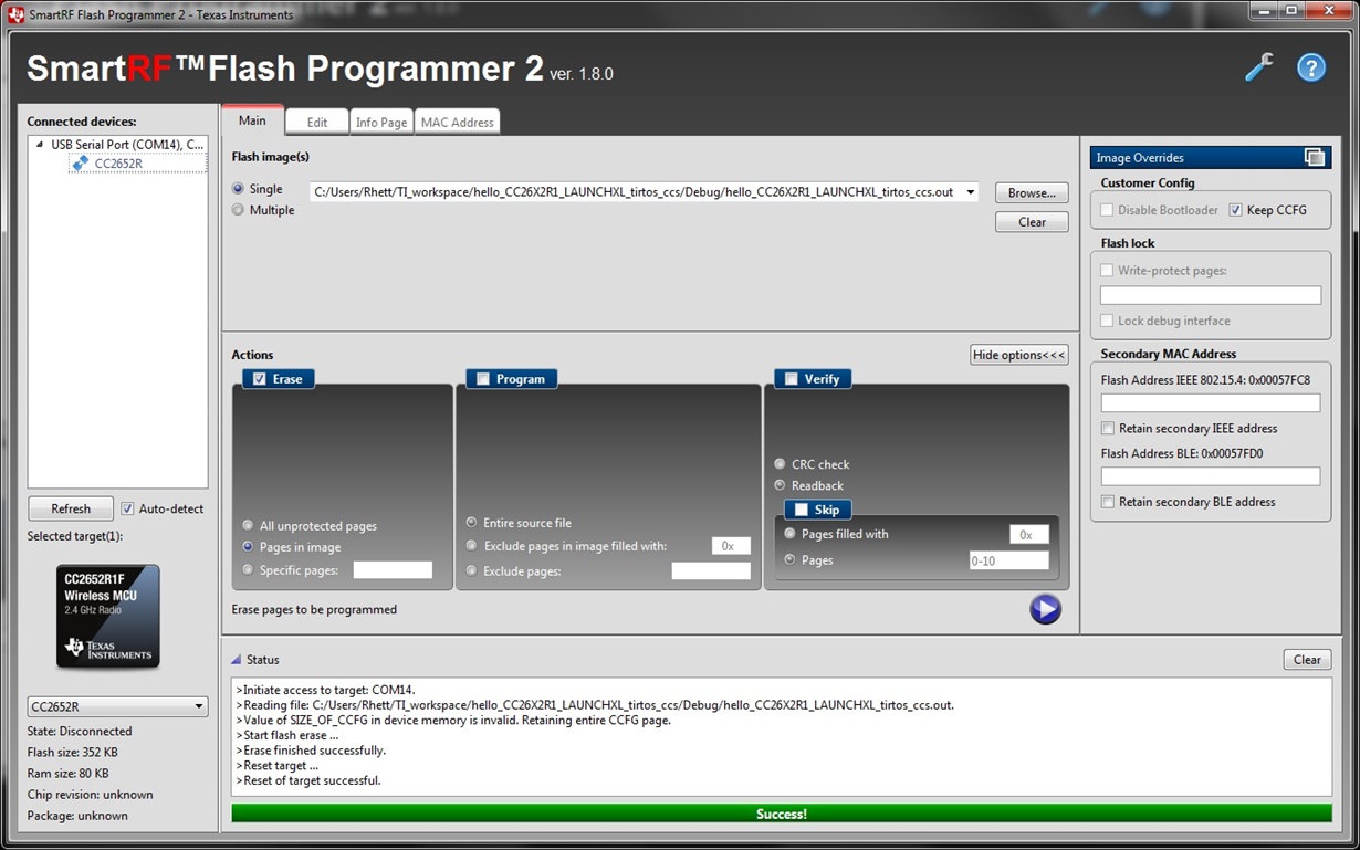
  • I working with a new board now, and I'm back to the original problem.  I can read and erase all I want, but programming still fails like so:  (also see various screenshots (read, erase, & attempted program) below)

    >Initiate access to target: COM14.

    >Reading file: C:/Users/Rhett/TI_workspace/hello_CC26X2R1_LAUNCHXL_tirtos_ccs/Debug/hello_CC26X2R1_LAUNCHXL_tirtos_ccs.out.

    >Start flash programming ...

    >ACK/NAK not received. Expected 0x00 0xCC or 0x00 0x33, received 0xFF 0x00.

    >Error during flash download.

    - Start address 0x00002958 (page 1).

    - Tried to transfer 252 bytes.

    - This was transfer 43.

    >Failed to erase target memory: Error code 1: Error during flash download.

    - Start address 0x00002958 (page 1).

    - Tried to transfer 252 bytes.

    - This was transfer 43.

    >Failed to write 11992 bytes to address 0x00000000.

    >Reset target ...

    >ACK/NAK not received. Expected 0x00 0xCC or 0x00 0x33, received 0xCC 0x00.

    >Failed to reset device. Error code 1: ACK/NAK not received. Expected 0x00 0xCC or 0x00 0x33, received 0xCC 0x00.

    It looks like a simple handshaking protocol is different than expected...  Although all other functions appear to work, so I don't quite follow why this is a problem.

    Any insight appreciated.

    I don't see the option in CCS8 to generate HEX output rather than the linker's elf file.  I found where to rename the output, but I don't see an option to change output format.

    Finally, as to your claim that "the default CCFG section is setup to not disable anything", I must disagree:

    The ccfg.c file from the hello world example (where I started) simply includes the default like so:

    #include <ti/devices/DeviceFamily.h>
    #include DeviceFamily_constructPath(startup_files/ccfg.c)

    Which then includes the ccfg.c file from C:\ti\simplelink_cc26x2_sdk_2_30_00_34\source\ti\devices\cc13x2_cc26x2_v1\startup_files\ccfg.c, and that file is set like so:


    #ifndef SET_CCFG_BL_CONFIG_BOOTLOADER_ENABLE
    #define SET_CCFG_BL_CONFIG_BOOTLOADER_ENABLE            0x00       // Disable ROM boot loader
    // #define SET_CCFG_BL_CONFIG_BOOTLOADER_ENABLE         0xC5       // Enable ROM boot loader
    #endif

    So, it appears to me that anything built with CCS8 & SDK 2_30 will default to disabling the bootloader unless you dig deep into the linked default config file.  And "Smart"RF Programmer will happily inform you that the CFG is set to lock the device -- but only AFTER it has already done so and there is no possible recourse.  A lovely combination to get start out with.  ;-/ 

    Which is exactly how I started -- just trying to get an example project working (to validate the flash tools) before starting any real development.

  • The latest error message indicate that your UART does not properly connect to the bootlader.

    What is the max baudrate of the FT234XD-R USB Bridge you use? I saw some similar error message in a different case where the UART was not fast enough to support the 400 kbaud flash programmer uses.
  • TER, I really don't think this is the case.  The FT234XD-R supports up to 3 Mbaud and syncs to just about any speed -- even non-standard ones.

    SmartRF Programmer2 can read then entire flash or the entire RAM in one (long) go with NO errors... read the config page, read the Ethernet & Bluetooth addresses, Erase pages, and even PROGRAM particular pages -- all without ANY errors.

    I can PROGRAM the device -- if I select "skip pages 0-10"... I am still leery of locking another chip, so I haven't experimented extensively with this, but I suspect it's probably just page 0 that is the problem.

    I suspect either a "0-related" bug in SmartRF Programmer 2, or some sort of hardware protection of page 0...  The error message does not look like it received garbled data, but rather like it just expected a different response from the CC2652R1F.

    Thanks much,

       --Rhett

  • If you look at www.ti.com/.../swra466a.pdf the bootloader should respond with a valid ack when trying to program the device. If you don't get this ack, the bootloader protocol is not running as it should and you will not be able to program the device.
  • Is there an option to get a log of the RAW USB communication?  Given that everything else communicates properly (and all those sequences include ACK/NAK as well), this really looks like a software problem to me (on one end or the other), but a RAW communciation log should make it fairly obvious as to what is going on.

    Is there an option to save a RAW USB log from SmartRF Programmer?

    Thanks,

       --Rhett

  • Hi,
    Unfortunately there's no option to save USB log from SmartRF Flash Programmer 2. You would then have to use a USB traffic sniffer, which typically requires expensive hardware.

    Using the serial bootloader on the CC13xx/CC26xx devices to program flash, it's important to be aware of the fact that the disable bootloader flag take effect immediately. The flag is placed in CCFG and is checked by the bootloader prior to executing any command. All other CCFG configuration does not take effect until after a device reset. The recommendation using the serial interface is to program your application which does not lock down the bootloader, and verify the integrity of the image. In a last, separate step, you lock down the bootloader.

    Can you share the application image you are trying to program (.hex, .out or .bin)? It will allow us to try reproducing the issue on our side and debug it.

    TIABO

  • I'm off-site at the moment, but I'll upload the .out file late this afternoon.

    We are trying to determine if there is anything significantly different about our hardware that may be causing the problem.

    What USB bridge chip does your test setup use?  Can you program the 2652 reliably over USB?

    What does the bootloader use for its clock?  Does it use the internal R/C oscillator?  Does it change to the crystal when programming?

    (Our H/W engineer noticed that our board still had the 24MHz crystal for the 2650 -- 48MHz ones are on order.)

    Finally I notice that SmartRF programmer has two 2652 chips in the drop down -- the 2652R and the 2652RB.  What's the difference?  Is there a new rev of Silicon?  (I didn't find it on your site.)  Or is it a different S/W mode/setting?  Should I be using that instead?

    Thanks,

       --Rhett

  • File attached.  It is a variation of one of your sample programs.  It just toggles between two LEDs every half-second.  I have #define (SCCB -- our custom board name) that toggles the red/green LEDs on the LaunchPad -- or on our custom board with the LEDs on DIO10 and 15 instead of on DIO6 & 7.

    Other than the TI-RTOS & includes, here is the entire program:  (It works fine on the LaunchPad.)

    /* XDC Module Headers */
    #include <xdc/std.h>
    #include <xdc/runtime/System.h>

    /* BIOS Module Headers */
    #include <ti/sysbios/BIOS.h>
    #include <ti/sysbios/knl/Clock.h>

    /* Example/Board Header files */
    #include "Board.h"
    #include "PINCC26XX.h"

    #define SCCB

    #ifdef SCCB
      #define LED1 IOID_10
      #define LED2 IOID_15
    #else
      #define LED1 IOID_6
      #define LED2 IOID_7
    #endif


    Clock_Struct clk0Struct, clk1Struct;
    Clock_Handle clk2Handle;


    /*
     *  ======== clk0Fxn =======
     */
    Void clk0Fxn(UArg arg0)
    {
      static int x = 0;

      PINCC26XX_setOutputValue(LED1, x);
      x = 1-x;
      PINCC26XX_setOutputValue(LED2, x);
    }


    /*
     *  ======== main ========
     */
    int main()
    {
        Board_initGeneral();                     // Call driver init functions

        PINCC26XX_setOutputEnable(LED1, 1);      // Enable LED Outputs
        PINCC26XX_setOutputEnable(LED2, 1);

        Clock_Params clkParams;
        Clock_Params_init(&clkParams);
        clkParams.period = 500000/Clock_tickPeriod;
        clkParams.startFlag = TRUE;

        /* Construct a periodic Clock Instance */
        Clock_construct(&clk0Struct, (Clock_FuncPtr)clk0Fxn, 5000/Clock_tickPeriod, &clkParams);

        BIOS_start();    /* does not return */
        return(0);
    }

    hello_CC26X2R1_LAUNCHXL_tirtos_ccs.7z

  • Hi Rhett,

    What kind of error message did you receive that the debug interface is locked? 

    Is this the file you attached to be used on the LP or your custom board? 

    I've tried programming the file on a CC2652R LP multiple times via USB without problems. But I've performed a mass erase over JTAG to program on an empty device.

    As far as I know, the bootloader uses the internal R/C oscillator.

    BR, 

    Elin 

  • Elin,

    Not sure I understand "debug interface locked"?  I got a message that the "device" was locked (e.g. the Bootloader was disbled) after programming the config sector the first time (I just didn't realize that the config sector was encoded in the CCS8 project until then -- and it defaults to locking out the USB bootloader.)  Basically that just means I bricked one of our custom boards with the very first U/L attempt.

    Not sure if the serial pass-through via the XDS-110 accurately mirrors a direct USB connection, but even so, why did you need to use JTAG to erase?  Can't you erase over USB?  What software are you using?  (UniFlash?  SmartRF Flash Programmer 2?  CCS8?)

    We are working on a seperate JTAG interface, but for now, USB is all I have, and only SmartRF Programmer is able to work at all... but not flash the complete image, only parts of it.

    Thanks,

       --Rhett

  • If you look at figure 1 in www.ti.com/.../swra466a.pdf : You can only access the bootloader if you don't have a valid image or have enabled the backdoor. Meaning that erasing via the serial interface is not straightforward since you will not be able to enter the bootloader in the first place.

    The XDS is connected to the UART pins in the same way as a different USB to UART device is meaning that you should not see any difference between the two.
  • Silly me, I would expect that an "erased flash" would be detected as "invalid" and therefore the bootloader would ALWAYS be entered after erasing the flash.  "swra466a.pdf" says it will enter the Bootloader if the Flash is invalid... but it fails to say what values of which bits it uses to determine if the flash is valid, only that it is 'determined by an “image valid” field in the customer configuration area (CCA/CCFG).'  But no explanation of where that field is or what values are expected for valid/invalid.  Not very useful.

    So overall, you're saying that I can't erase the flash using USB?

    (Not that Smart RF Flash Programmer even offers a "bulk erase" command.)  Therefore it isn't possible to program the device via USB because it can't be erased in the first place.  Why have a USB bootloader in the first place if it can't do this?

    ***** If it's possible, but just "not straightforward" as you claim, then I would greatly appreciate instructions for how to do it in whatever required "non-straightforward" manner will actually work.  *****

    This is still my main question/problem, and has been since the beginning.  Provide a workable method for programming via USB and we can close this thread.

  • Hi Rhett,

    The main intention behind the ROM bootloader is to use it for production programming.

    You can program the device through the ROM bootloader if:
    1) There is no valid flash image in the device (for details on the image valid field you can look in the Technical Reference Manual). - This would be the case for new devices coming from TI.
    2) If you have programmed the flash, and set CCFG settings such that the ROM bootloader is enabled and can be accessed by asserting an IO during boot.

    If neither of these are fulfilled it is not possible to enter the ROM bootloader and thus not possible to do a mass erase either. You can still erase the device through the JTAG interface though, unless you have deliberately disabled this option in CCFG.

    If you need the bootloader to support other features, we have a flash based version of the code available which you can customise to your needs. The code can be found here: github.com/.../ble_examples-2.2 (look for Serial_Bootloader).

    Regards,
    Fredrik
  • Fredrik,

    I understand the purpose of the bootloader.  I understand the basic operation of the bootloader.

      But. it. doesn't. work!

      Not even the first time.

    ...and the first time is generally the only time you get a shot at it (given the defaults in CCS8's config page).

    I can get it to program if I skip the first few pages... but it won't program the entire image.  I can read the entire Flash -- but NOT program it.  I can read config pages, erase pages, and program partial images -- but NOT the whole thing.

    Previous advice was "erase it with JTAG", and then program it with USB...  Which really defeats the purpose of having USB at all.

    Not sure why I continue this.  It's becoming pretty clear that no one will address the basic problem.

       -- Rhett

  • Rhett,

    Earlier in the thread you mention that your application works fine on the LaunchPad. Is the issue isolated to your custom board? We're able to program the file you shared using SmartRF Flash Programmer 2 and a LAUNCHXL-CC26x2R. To start with the basics, we used the debug interface (cJTAG or JTAG) to erase the flash. This ensures that the CCFG configuration enables the serial bootloader and that there is no "valid" image in flash.

    The serial bootloader is configured with several byte fields in the Customer Configuration area of the device (CCFG). CCFG is located at the uppermost flash page (highest address). At device boot, the bootloader configuration is read and the device enters bootloader mode if certain conditions are met. For example, the device will normally not enter bootloader mode if the CCFG field has a valid value (address is a valid Cortex-M reset vector address). Let me know if you have further questions on these conditions are unclear (details in the CC13x2/CC26x2 Technical Reference Manual).

    One important note is that the bootloader always reads CCFG::BL_CONFIG.BL_ENABLE prior to executing an incoming command. That is, changes to BL_ENABLE takes effect immediately, and not after a device reset (which is the case for the other bootloader configuration options). 

    Br,
    TIABO

  • For the benefit of others reading this thread:

    Despite all the various excuses from TI, the problem appears to have been a hardware power issue (an inline protection resistor on the USB power line) on our board.  I guess programming takes significantly more power than reading or even erasing -- causing a brown-out when programming.

    While I'm not surprised that we had some initial issues with new hardware, I am rather disappointed with the quality of support.  Even though TI often attempted to help, they rarely directly answered any of my questions, and often brought up other tangential issues.

    I am also very disappointed with how easy it is to lock or disable the TI devices without any warning -- and the defaults built into the SDK *ARE* set to lock the device (despite claims to the contrary from TI).  Not nice.  There appears to be several different ways to completely lock these devices.  Great for production, lousy for development.  I may have to write a validation program to check every image before programming it -- so I don't inadvertently lock up any more devices just because I tried using some code from the Resource Explorer.

    (Just compiling and downloading "Project Zero" to a TI 2650 SensorTag has destroyed it... just by hitting F11 in CCS8.)

    Anyway, I'm closing this tread...  consider the original problem solved, but I'm not very happy with the tools or support right now.

       --Rhett

  • Hi Rhett,

    It is good to hear that you resolved your issue. Are you saying that the board was reset due to voltage drop through U47?

    The settings in the SDK are not set to lock the device. All JTAG fields are set open, and you must actively change these to lock the JTAG interface.

    The ROM bootloader is intended for production programming. As stated in the documentation, and repeated throughout this thread, the bootloader is only available if the flash is empty or if you have actively enabled it. The reason behind this is that when the bootloader is enabled, anybody can read out your flash content. Hence, we do not recommend anybody to release products without locking the bootloader.

    The SensorTag you say is destroyed, is that because the JTAG interface or the bootloader interface is locked?

    Regards,
    Fredrik