This thread has been locked.

If you have a related question, please click the "Ask a related question" button in the top right corner. The newly created question will be automatically linked to this question.

CCS/LAUNCHXL-CC1352P: SPI Communication CC1352P

Part Number: LAUNCHXL-CC1352P
Other Parts Discussed in Thread: SYSCONFIG, CC1352P

Tool/software: Code Composer Studio

    Hi ,

        Hope you are doing good,
        
        I am working on the SPI module interfacing E-paper display. I have configure the pins using SysConfig tool 3 wire pin mode. and I am manually controlling

        the Chip Select pin using GPIO driver.
        
        My problem is I cannot see the CLK frequncy and data in MOSI pin in scope.
        
        let me know where i am stuck. here is my code and sysconfig setup as per too docs I done.

:

Please suggest me the solution.

  • Hi,

    Can you verify if the SPI example provided in you SDK is working as expected?

    Once you have validated the OOB example is working, you can slightly modify its configuration (through SysConfig) to use the hardware "LaunchPad SPI Bus" (in three pins mode).

    I hope this will help,

    Regards,

  •     Hi Clement,

            Thanks for your reply,

            I don' t have 2 boards to run the SPI example. I tried to see the response in DSO. But, No Signal.

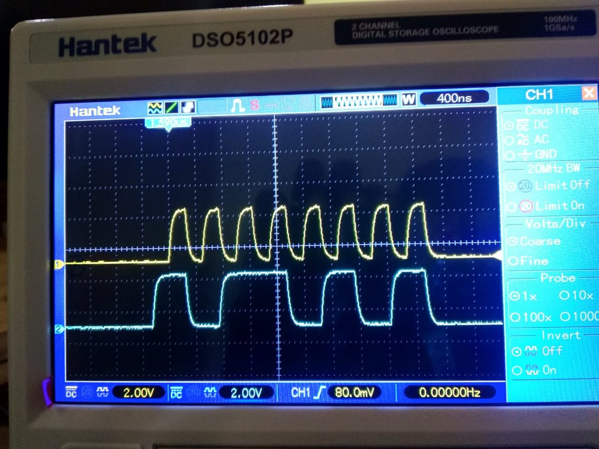
            and About the pin modification: Modified hardware SPI bus I can see some signals in DSO.
            
            I am sending 0x01 data continously for 50 times 2 sec each. My transfer count is set to 8.  
            
            Please have a look on the image.

            Yellow-CLK Blue- MOSI.

        Thank you,

  • Hi,

    Can you try to connect the MISO and MOSI line of the CC1352P and run the SPI example? I would like to be sure you can read/write data through the SPI.

    Please make sure that you are considering the right PINs.

    EDIT: The previous message has been edited. As a result, my recommendation might be outdated

    Regards,

  •     Hi Clement,

            Thanks for your reply,

            Clement Where to connect these pins ?  suggesting me to connect with other controllers? I am trying to interface e paper display.
            
            Yes, I am considering the correct pins MOSI(DIO9)- SDI, SCLK(DIO10)- CLK,  CS (Chip Select) I am configuring using GPIO, Considering (DIO11).

        Thank you,

  • Hi,

    So your SPI communication is working. Right?

    Now, you have to verify in the datasheet of your component which frame format is expected, which baud rate,... You can also use the logic analyzer to verify the value outputted on the CS line.

    Let me know what I can do to help you.

    If your issue is solved, please mark the thread accordingly.

    Kind regards,

  • Hi,

    I Choose SPI_MODE0 i.e. Frameformat 1 CPH=0 CPOL= 0 My slave supports this frame format. .

    And I have saw the SR register. please see the image. I have an error: unable to read . Do you thing this could be a problem?

    .

    Regards,

    Selva.I

  • Hi,

    Did you pause the execution when you took this screenshot? If not, your result is expected.

    Regards,

  • Hi,

    No, I didn't pause the execution.

    But I see this error while program execution and if I pause the execution.

    Regards,

    Selva

  • Hi,

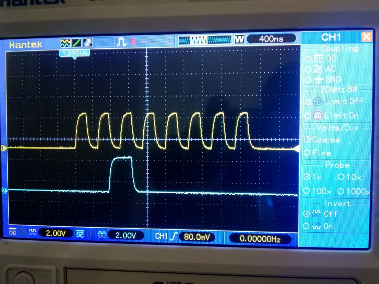
    Stil I am not getting the proper data in MOSI pin.Please have look on the image below. I am sending data 0x04, transaction count = 1;

    See the response. Is that correct?

    Please suggest me the best.

    Regards,

    Selva

  • Hi Selva,

    Two points:

    - the fact you cannot see the content of the registers using the debugger is not expected. Once the corresponding SSI module (i.e. SSI0 or SSI1) has been initialized (i.e after SPI_open() ), if you pause the execution, then you should be able to see the content of the registers. If this is not the case, that generally means the module is not properly powered (but I absolutely don't think this is the case here as you have the expected clock - TI drivers are responsible for powering properly the different modules used).

    - the data you are getting on the wire is obviously not the one expected.

    • Are you always getting this same value? Including if you change the value sent out?
    • Can you provide us the code snippet you are using to get this result?

    Best regards,

  • Hi Clement,

    Thank you for your reply, No I am not getting the same value. Please see the image shown below with the different datas.

    Data:0x04 now,

    Data: 0x03

    and my code:

    uint8_t data_r = 0x04;

    void *masterThread(void *arg0)
    {
       SPI_Params_init(&spiParams);
       spiParams.frameFormat = SPI_POL0_PHA0;
       spiParams.bitRate = 2000000;
       spiParams.mode = SPI_MASTER;
       spiParams.dataSize = 8;
       masterSpi = SPI_open(EPD_SPI0, &spiParams);
       if (masterSpi == NULL) {
           printf("Error initializing master SPI\n");
           while (1);
       }
       else {
           printf("Master SPI Opened\n");
       }

       for (i=0;i<sizeof(data_t);i++)
       {
           printf("CommandRegister = %d\n", i);;
           EPD_CommandrRegister(data_r);
           sleep(2);
           if (i==5)
           {
               printf ("App Close\n");
               break;
           }
           else continue;
       }
       printf("SPI_Close\n");
       SPI_close(masterSpi);
       while (1);
    }

    void EPD_CommandrRegister(uint8_t comm)
    {

      GPIO_write(Green_LED,1);
      transaction.count = 1;
      printf("data = %02x\n",comm);
      transaction.txBuf = (void *) comm;
      transaction.rxBuf = NULL;
      transferOK = SPI_transfer(masterSpi, &transaction);
      if (!transferOK){
          printf("Error Transfer\n");
      }
      else{
          printf("SPI Transferred\n");
      }
      sleep(1);
      GPIO_write(Green_LED,0);
    }

    I hope this will help you,

    Regards,

    Selva

  • Hi,

    I think the problem is coming from the line transaction.txBuf = (void *) comm;  

    The buffer is supposed to be pass by reference (not by value). Please consult the TI drivers documentation for further information.

    You can modify the line by:

    transaction.txBuf = &data_r;

    I hope this will help,

  • Hi Clement,

    Thanks it works for me,

    But I cannot send the data continously, I mean bulk of data. Should I give more delay in between the transfer ?

    Thank you,

    Regards,

    Selva

  • Hi,

    Glad to have found the issue! If you expect continuous transfers, you can play with two factors:

    • increase the amount of data sent in each transfer (it is non common to send only one byte for each transaction)
    • use the SPI driver in Callback mode and queue several transactions (this can be done calling several times SPI_transfer())

    Please consult the the TI drivers documentation for further information and examples.

    Kind regards,

  • Hi,

    Thanks for reply, 

    I am interfacing E-paper display So I need to send data one by one. Because I need to differ the data by CommandRegister and dataRegister.

    What I can do in this case ?

    Thanks,

  • Hi,

    user5392053 said:
    I am interfacing E-paper display So I need to send data one by one. Because I need to differ the data by CommandRegister and dataRegister.

    Then send the data one by one and wait the adequate time in between the call to SPI_transfer()

    Regards,

  • Hi Clement,

    I have given 3 second adequate time between each transfer. still i am not getting the same response. Can you help me in this ?

    Thank you.

  • Thanks all the problem solved

    Thanks for your support

    Regards,

    Selva.I