This thread has been locked.

If you have a related question, please click the "Ask a related question" button in the top right corner. The newly created question will be automatically linked to this question.

CC2650STK: Enable POWER_SAVING on CC2650STK SensorTag - zStack_home_1.2.2a

Part Number: CC2650STK
Other Parts Discussed in Thread: HDC1000, Z-STACK, CC2650, OPT3001, TMP007

Hi to everyone,

I have develop and managed the firmware for CC2650STK and now I would like to start making accurate test of Power Consuption.

In my case the features enabled on the CC2650STK are:

- JOIN to Coordinator (with AUTO-BIND enabled)

- REPORT of temperature (HDC1000)

- REPORT of acceleration (MPU9250)

And I want to disable every features on firmware (to save battery)...It's possible to disable POWER_SAVING on CC2650STK? and I want understand if the "data request polls to the coordinator" is enabled (variable ZNWK_POLL_RATE) by default on SensorTag application?

thanks

  • Data polling is enable by default and I don't know what you can prove with POWER_SAVING disabled.
  • thanks and I'm sorry...I was wrong...I wanted to say it is possible to enable POWER_SAVING on CC2650STK.

    And how do I disable "Data polling"? in sensortagapp.c what is the function to modify?

  • POWER_SAVING is enable by default in CC2650 Z-Stack Home 1.2.2a example. You can set POLL_RATE=0 to disable polling rate.
  • Ok, thanks...but which variable, ZNWK_POLL_RATE in znwk_config.h:

    /**
     * End Device Poll Rate -
     * The number of milliseconds to wait between data request polls to the coordinator.
     */
    #if !defined ( ZNWK_POLL_RATE )
      #define ZNWK_POLL_RATE 5000
    #endif

    or DPOLL_RATE in f8wConfig.cfg:

    /* The number of milliseconds to wait between data request polls to the coordinator. */
    -DPOLL_RATE=1000
  • -DPOLL_RATE in f8wConfig.cfg.
  • Ok ok...but my curiosity ... but this is an error:

    xIGHTSENSOR_ENABLED simbol is set by default in SensorTag application! I think it's xLIGHTSENSOR_ENABLED...related to the LIGHTSENSOR_ENABLED variable in SensorTag (?)

  • It’s a unused define so it doesn’t matter. If you want to enable it, it’s correct to use LIGHTSENSOR_ENABLED

  • Ok ok, thanks
  • another relative question: In this scenario (POWER_SAVING enabled, DPOLL-RATE = 0), after it joins a Zigbee network,I assume that CC2650stk would consume 3uA if there is no poll or send no message...

  • It depends if the sensors are shut down or not.
  • Ok, I know this...for example in SensorTag (original firmware) with only:

    #define DEFAULT_TEMP_REPORTING_INTERVAL 3600 // 1 hour

    the CC2650STK is not in sleep-mode when timer is expired, but between one execution and another yes, correct?
    Is there a way to turn off the sensors on board?
  • Yes, CC2650 is in sleeping between one execution and another. I remember sensors on board can be turned off but you have to check schematics by yourself.
  • Ok, I know...
  • in sleep-mode consumption is 3uA, correct...or is 3uA when all sensors are turned off?
  • I suppose it should be about 3uA when all sensors are OFF.
  • Ok ok...thanks.

    To TURN ON/OFF a specific on board sensor, I can simply use the driver functions.

    For example, for MPU-9250 use this function:

    /*******************************************************************************
    * @fn          sensorMpu9250PowerOn
    *
    * @brief       This function turns on the power supply to MPU9250
    *
    * @return      none
    */
    void sensorMpu9250PowerOn(void)
    {
      extern PIN_Handle hGpioPin;
    
      // Make sure I2C interface is in a known state
      bspI2cSelect(BSP_I2C_INTERFACE_0,0);
      bspI2cDeselect();
    
      // Turn on power supply
      PIN_setOutputValue(hGpioPin,Board_MPU_POWER, Board_MPU_POWER_ON);
      delay_ms(100);
      sensorMpu9250Init();
    }
    
    /*******************************************************************************
    * @fn          sensorMpu9250PowerOff
    *
    * @brief       This function turns off the power supply to MPU9250
    *
    * @return      none
    */
    void sensorMpu9250PowerOff(void)
    {
      extern PIN_Handle hGpioPin;
    
      // Make sure I2C interface is in a known state
      bspI2cSelect(BSP_I2C_INTERFACE_0,0);
      bspI2cDeselect();
    
      // Turn off power supply
      PIN_setOutputValue(hGpioPin,Board_MPU_POWER, Board_MPU_POWER_OFF);
    }

    And to verify this, I can use:

    /*******************************************************************************
    * @fn          sensorMpu9250PowerIsOn
    *
    * @brief       Return true if MPU power is on
    *
    * @return      none
    */
    bool sensorMpu9250PowerIsOn(void)
    {
     return PIN_getOutputValue(Board_MPU_POWER) == Board_MPU_POWER_ON;
    }

    Correct?

    Instead in my sensortagapp.c I use this driver functions:

    // Initialise the Motion Sensor driver
      sensorMpu9250Init();

    In my readConvertAccel function I use:

    Step 1:

    // Enable acceleromter readout
    sensorMpu9250Enable(mpuConfig | 0xFF);

    Step 2:

    // Read data from the Mpu9250 motion sensor
          ret = sensorMpu9250AccRead(&accelData.v.accel);

    Step 3:

    accel_X = sensorMpu9250AccelConvert(accelData.a[0]);
    accel_Y = sensorMpu9250AccelConvert(accelData.a[1]);
    accel_Z = sensorMpu9250AccelConvert(accelData.a[2]);

    Final step:

    send report to ZigBee Coordinator...

    And repeat this step every (for example 1 hour) defined in:

    #define DEFAULT_MOTION_REPORTING_INTERVAL   3600    // Motion Sensor Reporting Interval

    I do not use sensorMpu9250PowerOff() and sensorMpu9250PowerOff() function...

    thanks

  • Yes, you can use this off function.
  • ok, thank you...So I can use sensorMpu9250PowerOn() function before the read and convert operation and after use sensorMpu9250PowerOff() function...This for each cycle

  • thanks!...instead for hdc1000 there are no powerOn/powerOff functions...I use:

    sensorHdc1000Init()
    sensorHdc1000Start()
    sensorHdc1000Read(uint16_t *rawTemp, uint16_t *rawHum)
    sensorHdc1000Convert(uint16_t rawTemp, uint16_t rawHum, float *temp, float *hum)

    but I do not see functions to TURN OFF or ON...

  • If you look at the CC2650STK schematics, you will see that the MPU-9250 VDD is connected to the CC2650 DIO12 and therefore can be powered on/off. The SPH0641LU4H follows a similar connection to DIO13. The HDC1000 VDD however is tied directly to VDD and therefore cannot be controlled. This is the same for the BMP280, TMP007, and OPT3001.

    Regards,
    Ryan
  • yes...I have seen!...thanks
    So it's possible to TURN ON/OFF only mpu-9250!
    It seems logical to me, the accelerometer consumes the most energy of all sensors...and this is the most delicate part to manage to save energy! Correct?
  • That's the logic behind the schematic decisions, yes.

    Ryan
  • although for tmp007, BMP280 and for opt3001 would seem possible in terms of driver functionality...and as described:

    /*******************************************************************************
     * @fn          sensorOpt3001Enable
     *
     * @brief       Turn the sensor on/off
     *
     * @return      none
     ******************************************************************************/

    /*******************************************************************************
    * @fn sensorTmp007Enable
    *
    * @brief Turn the sensor on/off
    *
    * @return none
    ******************************************************************************/

    /**************************************************************************************************
     * @fn          sensorBmp280Enable
     *
     * @brief       Enable/disable measurements
     *
     * @param       enable - flag to turn the snesor on/off
     *
     * @return      none
     */

    and have a different meaning on CC2650STK because unfortunately the schematic is that!
  • Enabling/disabling a sensor using the I2C interface is different from physically turning it on/off, if you look at the functions then you would notice that they are writing to registers instead of changing pin states.

    Regards,
    Ryan
  • Ok, I was seeing just that!

    last questions:

    1. The sensors directly connected to VDD (not controllable) practically always in sleep-mode (if I'm not going to use them in my application)?
    2. The MPU9250 sensor can TURN OFF/ON, but the SPH0641LU4H sensor, since it is not used right in the SensorTag application, will be turned off, right? I'm not going to write the status of the DIO_13 power pin to a high value (VDD), so it should already be turned off, I think...

    thank you so much!

  • 1. Yes
    2. This seems correct but you should verify by checking the pin level during operation, or at least confirming that it is driven as an output low inside the pin initialization table

    Regards,
    Ryan
  • In fact in Board.c file (located in : \ti\tirtos_simplelink_2_11_01_09\packages\ti\boards\SensorTag\CC26XXST_0120):

    PIN_Config BoardGpioInitTable[] = {
        Board_LED1       | PIN_GPIO_OUTPUT_EN | PIN_GPIO_LOW | PIN_PUSHPULL | PIN_DRVSTR_MAX,     /* LED initially off             */
        Board_LED2       | PIN_GPIO_OUTPUT_EN | PIN_GPIO_LOW | PIN_PUSHPULL | PIN_DRVSTR_MAX,     /* LED initially off             */
        Board_KEY_LEFT   | PIN_INPUT_EN | PIN_PULLUP | PIN_IRQ_BOTHEDGES | PIN_HYSTERESIS,        /* Button is active low          */
        Board_KEY_RIGHT  | PIN_INPUT_EN | PIN_PULLUP | PIN_IRQ_BOTHEDGES | PIN_HYSTERESIS,        /* Button is active low          */
        Board_RELAY      | PIN_INPUT_EN | PIN_PULLDOWN | PIN_IRQ_BOTHEDGES | PIN_HYSTERESIS,      /* Relay is active high          */
        Board_MPU_INT    | PIN_INPUT_EN | PIN_PULLDOWN | PIN_IRQ_NEGEDGE | PIN_HYSTERESIS,        /* MPU_INT is active low         */
        Board_TMP_RDY    | PIN_INPUT_EN | PIN_PULLUP | PIN_HYSTERESIS,                            /* TMP_RDY is active high        */
        Board_BUZZER     | PIN_GPIO_OUTPUT_EN | PIN_GPIO_LOW | PIN_PUSHPULL | PIN_DRVSTR_MAX,     /* Buzzer initially off          */
        Board_MPU_POWER  | PIN_GPIO_OUTPUT_EN | PIN_GPIO_HIGH | PIN_PUSHPULL | PIN_DRVSTR_MAX,    /* MPU initially on              */
        Board_MIC_POWER  | PIN_GPIO_OUTPUT_EN | PIN_GPIO_LOW | PIN_PUSHPULL | PIN_DRVSTR_MIN,     /* MIC initially off             */
        Board_SPI_FLASH_CS | PIN_GPIO_OUTPUT_EN | PIN_GPIO_HIGH | PIN_PUSHPULL | PIN_DRVSTR_MIN,  /* External flash chip select    */
        Board_SPI_DEVPK_CS | PIN_GPIO_OUTPUT_EN | PIN_GPIO_HIGH | PIN_PUSHPULL | PIN_DRVSTR_MIN,  /* DevPack chip select           */
        Board_AUDIO_DI | PIN_INPUT_EN | PIN_PULLDOWN,                                             /* Audio DI                      */
        Board_AUDIODO | PIN_GPIO_OUTPUT_EN | PIN_GPIO_HIGH | PIN_PUSHPULL | PIN_DRVSTR_MIN,       /* Audio data out                */
        Board_DP2 | PIN_INPUT_EN | PIN_PULLDOWN,                                                  /* DevPack */
        Board_DP1 | PIN_INPUT_EN | PIN_PULLDOWN,                                                  /* DevPack */
        Board_DP0 | PIN_INPUT_EN | PIN_PULLDOWN,                                                  /* DevPack */
        Board_DP3 | PIN_INPUT_EN | PIN_PULLDOWN,                                                  /* DevPack */
        Board_DP4_UARTRX | PIN_INPUT_EN | PIN_PULLDOWN,                                           /* DevPack */
        Board_DP5_UARTTX | PIN_INPUT_EN | PIN_PULLDOWN,                                           /* Devpack */
        Board_DEVPK_ID | PIN_INPUT_EN | PIN_NOPULL,                                               /* Device pack ID - external PU  */
    
        PIN_TERMINATE
    };

    Right now I'm checking that the battery dies in 1 month with the original SensorTag fw (zstack_home_1_02_02a_44539) as stated in a previous post by @YiKai

    In my case I will not use TMP007 (even because obsolete) but only HDC1000 and MPU9250 (accelerometer only, with REPORTING_INTERVAL = 3600).

    thanks ;-)

  • What is the power consumption you see now when device is in sleep mode?
  • with the original firmware (zstack_home_1_02_02a_44539)? I have to remount the circuit to see from an oscilloscope...
  • No, I mean the power consumption after you make so many modification.
  • I'm checking both: with the original version and with my version...but I have to reassemble the circuits to see by oscilloscope...I will update you!
  • I did the test and the battery (CR2032) died in 2 days with the original SensorTag application fw zstack_home_1_02_02a_44539).

    with:

    #define DEFAULT_ILLUM_REPORTING_INTERVAL 3   // 3 secs - Illumin (Lux) Sensor Reporting Interval

    #define DEFAULT_TEMP_REPORTING_INTERVAL 10 // 10 secs - IR Sensor Reporting Interval

    and LIGHTSENSOR_ENABLED disabled!

    I only set:

    staTsDstAddr.addrMode = zstack_AFAddrMode_SHORT;  // zstack_AFAddrMode_NONE;
    staTsDstAddr.addr.shortAddr = 0; // coordinator short address = 0x0000
    staTsDstAddr.endpoint = 0; // coordinator Destination End-Point = 8
    staTsDstAddr.panID = 0;

    to be able to send reports to the Coordinator.

  • Do you use power Analyzer to check power consumption details?
  • Now I put the circuit to perform the analysis...
    But maybe the battery (CR2032) could last 1 month without that modification (staTHsDstAddr.addrMode = zstack_AFAddrMode_SHORT) and then without sending anything to the coordinator (but only JOIN operation), correct?
  • If the device doesn’t join any Zigbee network, I suppose it will keep sending beacon requests and I think CR2032 will be drained up soon.
  • ok ok this is clear...in my case:
    I connect to the zigbee network (JOIN) and I have enabled the AUTO-BIND for tmp007 (receive data every 10 seconds)
  • What’s your question?
  • I just want to understand if to make the battery last 1 month I just have to set only CHANNEL and PANID (to make the CC2650STK perform the JOIN)? and without sending the reports from CC2650STK to the coordinator?
  • Do you mean to make CC2650STK keep sending beacon requests to join a Zigbee network and want CR2032 can last 1 month?
  • No, no...my CC2650STK correctly performs the JOIN with the zigbee network (it only sends the beacon requests in the start phase, after it joins and does not send anything anymore). So the C2650STK once the JOIN has been done it does not have to do anymore nothing (it should not send tmp007 reports)...only in this condition the battery dies in 1 month, right?
  • It depends on your application. If you set polling rate to 60 seconds and only send temperature data when it is necessary, I suppose CR2032 can last several months.
  • Yes, I think this too!...
    With the settings I see on the original firmware:
    - polling rate is setted to 1000 ms (-DPOLL_RATE in f8wConfig)
    and:
    #define DEFAULT_TEMP_REPORTING_INTERVAL 10 // send report every 10 seconds

    In this case the CR2032 is dead after 2 days

    But for my application (as mentioned before) I will disable the data polling (-DPOLL_RATE = 0) and since I need to send a temperature report every hour ... in this case even better and I think the battery could die after months, or I'm wrong?
  • If you disable the data polling (-DPOLL_RATE = 0) and since I need to send a temperature report every hour, the battery should last more than a month.
  • It's clear...thank you so much!
    surely (under these conditions) adding also the accelerometer (for example, by carrying out 10 readings and sending only MIN, MAX and AVG) the conditions are definitely more critical...

    A different question:
    Do you know if there are energy harvesting chip on the market for self-supplying modules (like the CC2650STK)?
  • No, I don’t know any energy harvesting chip on the market for self-supplying modules.
  • Hi YiKai,

    below the tests and consumption measures I have done:

    TEST 0 (zstack_home_1_02_02a_44539, ORIGINAL FW):

    Notes: MPU initially on in BoardGpioInitTable (Board.c file)

    After the successful JOIN:

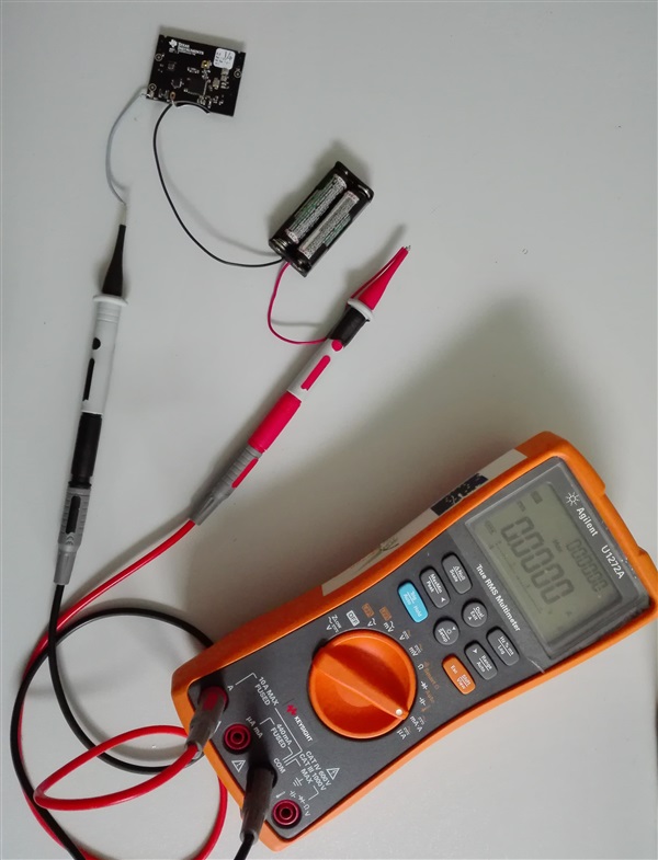
    with MPU POWER ON. So about 3 mA continuous...that's why the battery in my previous test in fact died after about 2 days (assuming a capacity of 200 mAh aprox).

    If instead MPU is initialized to OFF, after the successful JOIN:

    And during the operation of read, convert and SEND_REPORT (tmp007) I measured approximately:

    TEST 1 (my FW):

    Notes: Including hdc1000 and MPU9250 sensors, with the following active features:

    - HDC1000: reading and converting temperature and sending the report (every 1 hour) to ZC.

    - MPU9250: 200 readings and conversions of X, Y and Z accel (duration of operation 1 second aprox) and sending MIN, MAX and AVG (every 1 hour) to ZC.

      Using the sensorMpu9250PowerOn(), sensorMpu9250PowerOff() and sensorMpu9250PowerIsOn() driver functions...to save energy (and MPU initially off in BoardGpioInitTable (Board.c file)).

    The result is similar to those of the TEST 0:

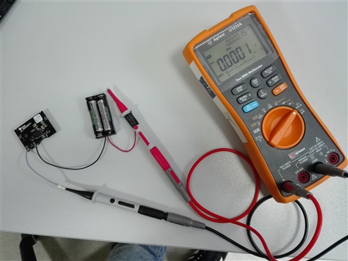
    during the operation of read, convert and SEND_REPORT (hdc1000) I measured approximately 0.0001 A.

    And during the operation of reading, conversion (200 operation in loop) and sending the report (MIN, MAX and AVG values) I measured as max value about 0.0035 A.

    With the oscilloscope I do not see values of the order of microAmpere...but I suppose that when the module is in sleep-mode, I have to consider the sum of all the contributions of the powered modules and in sleep mode (from datasheet), Correct?

  • According to your description, I suppose the power consumption comes from MPU9250 and you should check it first.
  • yes, practically yes...in fact, in my case every hour:
    step 1. Turn ON MPU9250
    step 2. Enable config for MPU9250
    step 3. Reading and conversion operation
    step 4. Turn OFF MPU9250
    step 5. Send report (MIN, MAX and AVG)

    and when MPU is turned off...the consumption is null pratically!
  • I suppose " when MPU is turned off...the consumption is null pratically!" means power consumption is very low, right? If so, the power consumption depends on how long to turn on MPU9250.