This thread has been locked.

If you have a related question, please click the "Ask a related question" button in the top right corner. The newly created question will be automatically linked to this question.

SMARTRF06EBK: SmartRF06 Evaluation Board to program an external Target

Part Number: SMARTRF06EBK
Other Parts Discussed in Thread: CC2538

I'm using the SmartRF06 (EVM) to program an external target (CC2538NF23).

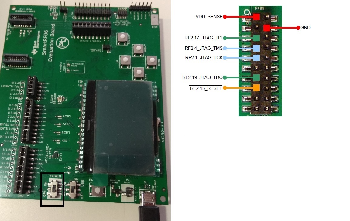
Jumpers and JTAG pins are connected according to document swru321b.

I programmed the flash memory succesfully and the program runs (a simple blink on a GPIO pin) but when i disconnect the power of the EVM the program stops working although they still have power supply (all this with the JTAG wire connected to the PCB where i have the CC2538). The program starts working again if i connect the EMV board and i open the program SmartRF Flash Programmer 2 (advance mode LED of the board turns on).

Moreover if i only disconnect the JTAG header the program keeps running until it is reset or the power supply is shut down.

i don't know why is only working when i have the EVM connected. Advance Mode is doing something in the bootloader? The problem could be in the memory mapping?

Anyone has a clue of what is happening?

Thanks. 

Melvin.

  • Could you post a picture that shows your setup and highlight how you disconnect the power to the EVM. Also could you clarify this: " disconnect the power of the EVM the program stops working although they still have power supply" How can you disconnect power and still have power?
  • Sorry about the misunderstood.

    The power supply that has the CC2538 (a battery) is independent of the supply voltage of the EVM (the source voltage is via USB).

    So when i switch off the EVM using the power switch of the EVM board, the program of the CC2538 stops.

    I don't know how could affect switch off the EVM board to the behaviour of the CC2538 if it has his own power supply and the EVM is only sensing the supply voltage of the CC2538 by pin 1 of JTAG. In this operation JTAG is connected to the pins of CC2538 as is specified in documents. 

  • I see that I got confused by you use of EVM. SmartRF06 is a EB (Evaluation Board) where you can comment a EVM (evaluation Module) to the EM connectors. As I read your text you have a custom board that you connect to the EB through the JTAG interface.

    When you turn off the power on the EB, is the reset pin defined? It could be that some of the jtag pins for some reason get into a strange state if this is not powered?
  • Seems that EB resets the CC2538 if EB is turned off. This will explain why is still working if i disconnect the JTAG. Other pins are not in a strange state. (JTAG_TCK = 0V | JTAG_TDO = Vcc | JTAG_TMS = Vcc | JTAG_TDI = Vcc).
    But to start again the program after a reset in the CC2538, the JTAG, the EB and the program SmartRF Flash Programmer 2 need to be connected.
    i am wondering if some data is sent through JTAG at the start when EB is power up that change something in the bootloader or the boot order of the CC2538.
  • Don't think this should affect the bootloader.

    But in the end you want to run the code on your board without the jtag interface connected so is this a important issue?
  • I was wondering why it is not working without the JTAG.
    I runned some other tests and i realized that some perturbation in the power supply of my PCB provoques the execution of the program in the CC2538. The JTAG connector attached to the EB board does some perturbations but by connecting and disconnecting the JTAG with the EB power off i have the same result.
    So the problem is not in the EB, is in why my code programmed in the flash of the CC2538 is not running when i power up the PCB and only a perturbation in the power supply trigger the programmed code.

    Any clue about why the programmed code get stuck at the start?

  • What could happen if you have something connected to the TCK is that if the chip could get noise on this pin which could be seen as clock pulses by the chip. If more than 8 pulses are received the chip could think it's in bootloader mode. You can try to tie this pin and see if you get the same issue.
  • I fixed TCK pin to gnd and the code didn't start after a reset. I'm still looking for the problem. In other PCB design the behaviour is correct with the same software so i don't know if the problem is in the hardware of the PCB i'm testing.
  • I could do a quick schematic/ layout review to see if I can see if something looks incorrect. If you don't want to post the design open on the forum, send me a friend request. 

    If I understand you correct, you have a different PCB that runs the same software and that you connect in the same way and that runs but not the PCB you are testing now?

  • Exacly. The other PCB has another design and it works with the same software. So if you can take a look to the schematic / layout of the PCB i'm testing, the one is not working properly. I will send it by private.
  • Friendship request accepted
  • Looking at your schematic: How do you ensure that the reset pin on CC2538 is pulled high if you don't have the JTAG connected?
  • I suppose that reset pin has an internal pullup resistor. It's fixed at Vcc supply if no reset is applied to the pin. Moreover, typical application schematics only presents a RC filter and no external pullup resistor.
  • I guess the question is if the internal pull-up is strong enough.

    What is the delta between this board and the board that works with regards to the JTAG and interface connection?
  • The JTAG circuit is the same in both cases. Although the perturbations i made was through the JTAG pins, seems to be a problem in gnd or power supply more than JTAG connections.
    I can try to put an external strong pull-up resistor in the reset pin.
  • Please let me know if that works. I didn't see anything else on the schematic/ layout that indicate issues with the JTAG interface.
  • I put 1k pullup resistor and It doesn't work. 

  • You write that you think it's a issue with gnd/ power more than the jtag interface itself. Is it some differences here on how you have done the layout and the power part of the schematic with the working and not working board?
  • I'm sorry to respond so late, but I was trying to figure out why the PCB that worked also stopped working. So i cannot give any clue about the difference between them because seems that also doesn't work properly same as the previous one. After a reset, the code is not initialized.
    But it's weird because i was working in that PCB for a long time and it didn't give me any problem.

    I have another PCB that has the same PCB design and it works fine with different firmwares, so i suppose that the problem is in the hardware.
    The CC2538 is sensitive to static or somehow an external weird thing can cause this problem?
  • From the information given I'm not able to figure out why you get this issue. To be able to help you further I would need the actual hardware but that require that the potential volume of this project is large enough.