This thread has been locked.

If you have a related question, please click the "Ask a related question" button in the top right corner. The newly created question will be automatically linked to this question.

CC2592: Lost output power when BAW filter was added

Part Number: CC2592
Other Parts Discussed in Thread: CC8520, , CC1190

Hello,

We recently revised our board designs (CC8520 + CC2592) to incorporate a Wifi + LTE coexistence filter (Qorvo QPQ1907).  The filter was found to immensely improve our wireless range when trying to operate near cell towers.

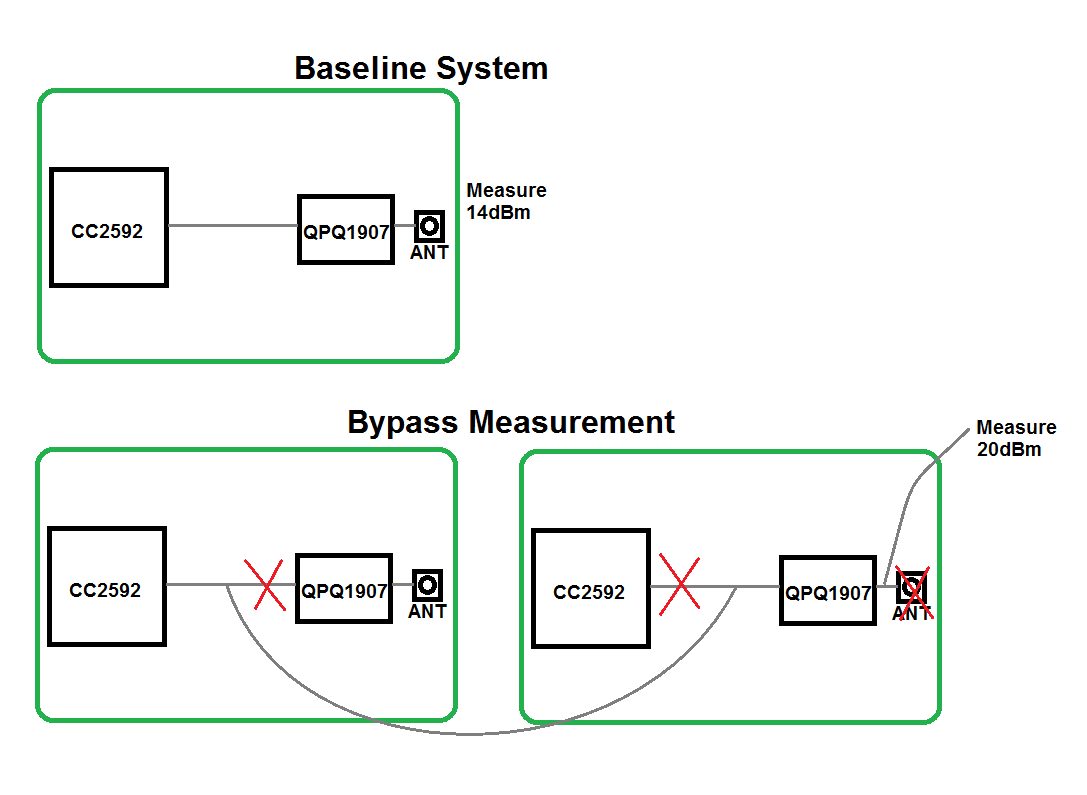
I seem to be finding that the filter drops our conducted power substantially.  Where we were getting over +20dBm in the old boards, now we're only seeing around +14dBm in the new boards.  If I modify a new board to bypass the filter, I get the +20dBm back.  The insertion loss for the filter shouldn't be more than about 1.5dB, and I confirmed this via network analyzer on a modded board, so I don't have an explanation for where the power has gone.

The suggestion I wanted to offer to TI for comment is, could the steep rejection of the QPQ1907 filter at the CC2592's harmonics be causing a problem that upsets the PA?  I saw posts elsewhere on these forums where TI mentioned that performance at the harmonics was key so that seemed like a possible explanation.  Could you look at my schematic and the filter datasheet and let me know?

By the way we have both a transmitter board and a receiver board that are now using the QPQ1907 + CC2592 + CC8520.  Both boards show the same behavior (old rev had +20dBm, new rev has +14dBm, new rev goes up to +20dBm if the filter is bypassed).  Let me know if I can provide more data for you.

edit: link to the post that mentions harmonics

https://e2e.ti.com/support/wireless-connectivity/zigbee-and-thread/f/158/t/662482

Thanks,

Arthur

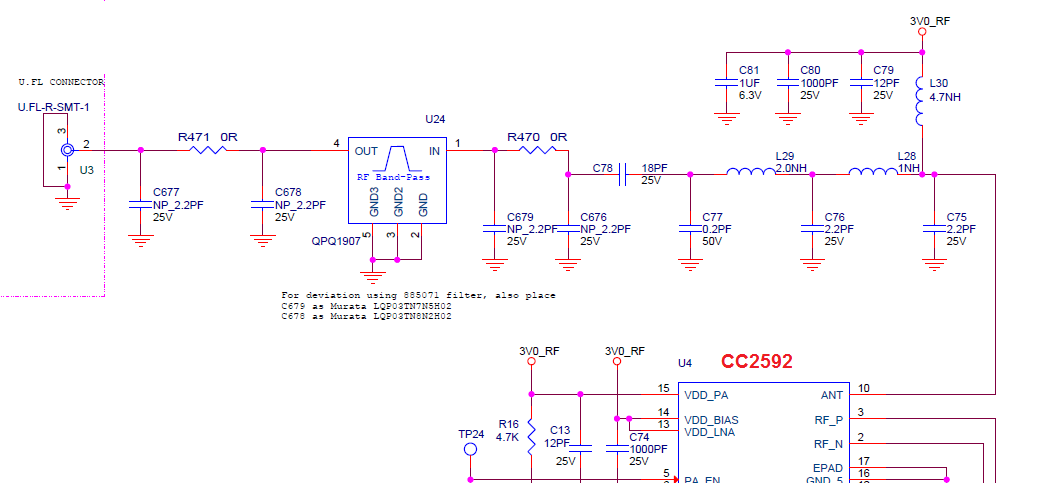
  • With regards to harmonics: The post you link to are basically discussing what impedance the ANT output has to see in addition to have the correct filtering. In your case the C78 is a 50 ohm interface and you should be able to connect a 50 ohm interface device to this without loosing power.

    If I understand your schematic correctly, C677, C678, C679, C676 are not mounted?

    And if you remove R470 and measure at the output of C78 you get +20 dBm?

    If that is the case I can't see anything in the schematic that should explain the 6 dB power loss. When you measured the filer, did you remove R470 and measured from that point and to the SMA?

    Not sure if it will give any information that can be used but are you able to measure S21 from the ANT output (with the CC2592 removed) to the S21 and compare with the S21 from R470 to the USB? The only thing I can think of at the moment is if the layout (grounding of the filter ?) impact in some way. The ground connection between different part of the board?
  • Hi TER,

    I will go line by line to your reply:

    With regards to harmonics: The post you link to are basically discussing what impedance the ANT output has to see in addition to have the correct filtering. In your case the C78 is a 50 ohm interface and you should be able to connect a 50 ohm interface device to this without loosing power. 

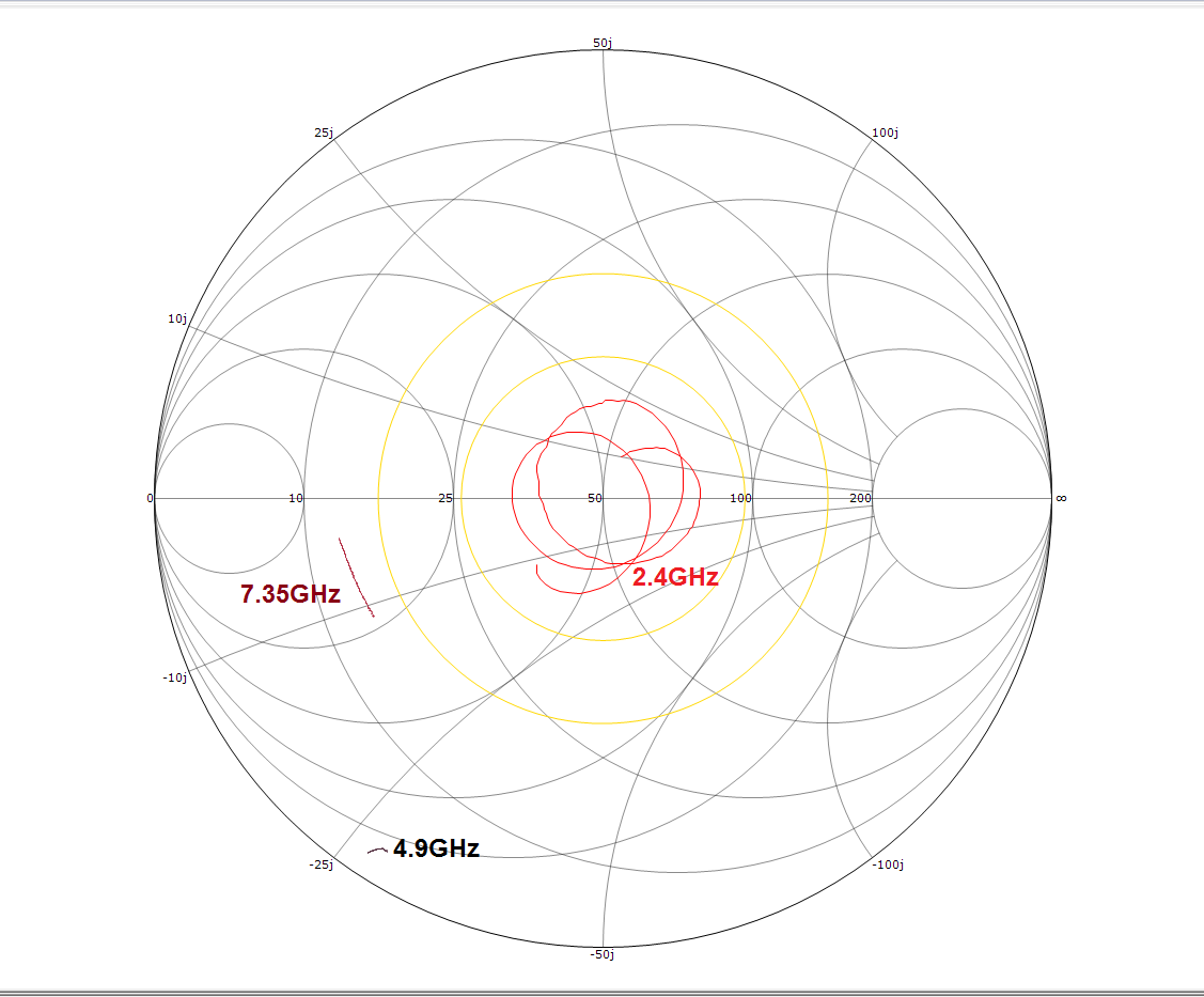
    The filter is 50 + j0 ohms at 2.45 GHz, but at 2nd harmonic 4.9GHz it's more like 5 + j0 ohms...

    If I understand your schematic correctly, C677, C678, C679, C676 are not mounted? 

    Correct

    And if you remove R470 and measure at the output of C78 you get +20 dBm? 

    Correct

    If that is the case I can't see anything in the schematic that should explain the 6 dB power loss. When you measured the filer, did you remove R470 and measured from that point and to the SMA? 

    Yes, just opposite side of R470 from when I measured the +20dBm power

    Not sure if it will give any information that can be used but are you able to measure S21 from the ANT output (with the CC2592 removed) to the S21 and compare with the S21 from R470 to the USB? The only thing I can think of at the moment is if the layout (grounding of the filter ?) impact in some way. The ground connection between different part of the board?

    Are you sure that makes sense?  Because the CC2592 ANT pin is not a 50 ohm output, and I would be hooking up a 50 ohm network analyzer in its place.  I haven't done this yet but it's possible.  I also suspect layout having some impact but I can't figure out what it might be.

  • For the last question: I think so. I have worked a lot with CC1190 (the sub 1 GHz equivalent to CC2592) and when I have simulated the network I have always used 50 ohm source. Note that this test is to find the transfer function of the network from the ANT point to the antenna connector (without the CC2592 mounted) Measuring this with the BAW filer in place you should see 6 dB attenuation more than if you measure just to R470. If that is the case it could potentially be possible to to some more measurements to see what causes the extra drop.

    If you like I can also take a look at the layout to see if I see something that looks strange (you can send me a friend request to allow you to send the gerber files privately )
  • Hi, did you see my private message last week with a link to the design files?

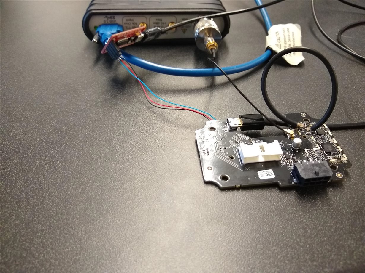
    I did another interesting test.  So far I know that my existing design only outputs about +14dBm when the CC2592 is connected to the filter.  And when I bypass the filter, I get over +20dBm.  The new test I did was to bypass the filter on one board, and connect that output via a coaxial cable to the filter section on a second copy of the same board.  (This second board had previously been set up for S12 testing, so its filter section was disconnected from the whole rest of its RF circuit).   In this configuration I got +20dBm output power.  So basically the only setup difference responsible for the improved output power was that I added a length of coaxial cable (6" or so) between the CC2592 output and the filter.  

    I'm again wondering if this could have something to do with the load that the filter presents to the CC2592.

  • Interesting test. To check the impedance theory, is it possible to remove R470 and insert something you know is 50 ohm? (you can use coaxial cable as you did in the previous test to be able to insert something here) It could be a 3 dB attenuation or something else.

    I can't see anything on the layout that could explain this.
  • I have done this already, by connecting a 50 ohm spectrum analyzer in place of R470. In that case I measured 20dBm output.

    Unless you are talking about inserting something I know is 50 ohm in the 2-board setup?
  • I want you to still measure the output of the BAW but replace R470 with something that represent a 50 ohm interface.
  • Hi,

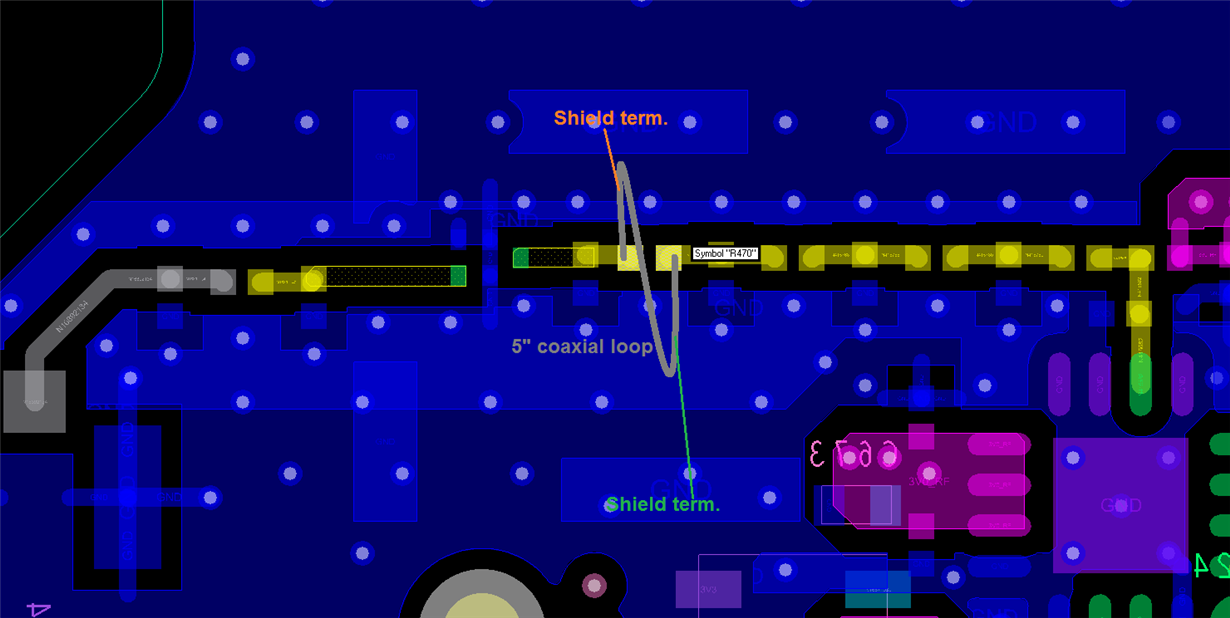
    With the above setup I measured 18dBm conducted power.  So still below the 20dBm I was expecting, but adding the 5" length of 50 ohm coaxial cable between the CC2592 and the QPQ1907 filter has increased the conducted output power up from around 14dBm previously.

    Do you think the best theory is that the radio is reducing its output power when it sees the filter as a load?  The only other explanation is that the radio outputs its full power but it several dB are lost by the time it gets to the connector.

    Thanks,

    Arthur

  • The tests indicate that when the CC2592 sees a 50 ohm interface (not the filter) you get the expected output power.

    If you look at our reference designs using CC1190 we actually have matching before the SAW filter since we have found that the filter we have used is not 50 ohm at the fundamental even though the datasheet state this. The tests indicate that the filter is not 50 ohm and hence a power loss.

    COuld be that I overlooked something but it looks like you have measured S21 through the filter but not S11/ S22?
  • Hi,

    I can share some plots and data files for S11 from the radio side of the filter.

    I went ahead and looked at S11 at 2.45 GHz, as well as the 2nd harmonic 4.9 GHz and 3rd harmonic 7.35 GHz.

    FILT_INPUT_S11.zip

  • I also wanted to add that the VSWR for the 4.9GHz band shown above is over 25. (VSWR for 2.4GHz band is under 1.5). CC2592 datasheet says VSWR under 7.5 is required for stability, but I don't know if this is relevant to the harmonics.
  • Hi Arthur,

    Have been discussing your case with TER. Can you try the following ?

    In the QPQ1907 app note, Figures 4a & 4b, pin 5 and pin 2 GNDs are deliberately not connected but in your design they are connected together on the top layer. Can you cut the GND between these two pads to see if this helps ? The QPQ1907 recommends not to route underneath the BAW.

  • Hi,

    I have checked carefully with Qorvo and the recommended design is indeed to connect ground underneath the filter. That is the way it is (bridged underneath on layer 1) on their eval board gerbers.

    Thanks,
    Arthur
  • Hi,

    Do you have the gerbers for the Qorvo BAW ref design board ?

    This seems contradictory to Figure 4a. I would still cut the tracks on the top layer between pin 2 & 5, just to test it since this is according to Qorvos app note Figure 4a.

    Regards,
    Richard
  • Hi,

    The Gerbers themselves I can't find online, I got them directly in an email so I'm not sure I should post them here. However if you download this datasheet and zoom in on the layout picture on page 3, you can see ground connected underneath on the top layer.

    www.qorvo.com/.../da006450


    I may be able to try the board modification but it will be tricky on this tiny part so it's more of a last resort. Reminder here that in the setup where I hooked two of my boards together (radio from the first board into filter from the second board) I saw my output power increase back up to over +20dBm.

    Thanks,
    Arthur
  • I'm starting to think you may be on to something, that the impedance on the harmonics for some reason could cause an issue. I have reach out the the designer that made the PA on CC2592 to get his feedback but I suspect that he is out of office this week. I will see if he is in on Monday.
  • Awesome thank you!

    I have tried a bit of tuning on the connection between PA and filter. I actually just added a 15 ohm resistor in series between them to try to reduce VSWR for the 2nd and 3rd harmonic while not messing up the 50 ohm impedance of the fundamental too much. This actually did increase my output power a bit, from 14dBm up to 18dBm, but not all the way back up to +20dBm. Real world audio streaming testing of this tuning didn't show any clear benefit to range by doing this though so I'm still scratching my head.

    Thanks,
    Arthur
  • I talked to the designer of CC2592 but he did not have any initial theories on what you see.

    I tried to see from the datasheet if the QPQ1907 requires a zero DC voltage or not. I was wondering if it would make sense to try different values of C76 or remove it (most likely a longshot). Btw, Have you measured that R470 actually is close to 0 ohm @2.4GHz?

    We have no experience with the behavior in this case. We have tested with different loads on the CC2592 output doing load-pull but then both the fundamental and harmonics have the same impedance.
  • Part Number: CC2592

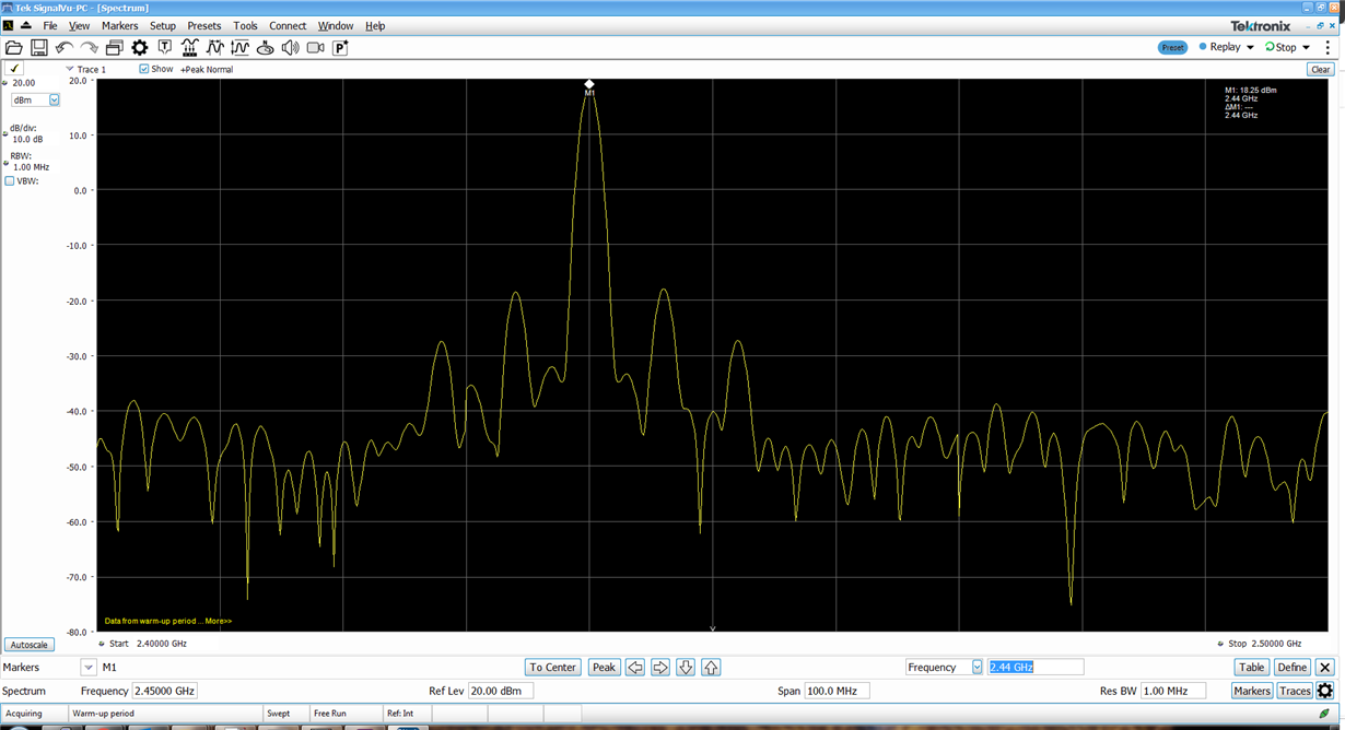
    Hi, I'm seeing spurs at approximately 1.2GHz and 3.6GHz, same as the linked question.  The other question was moved to private messages, can you please let me know if a resolution was found?

    Thanks,

    Arthur

  • Hi Arthur,

    The spurs you are seeing are half harmonic spurs that come up if the matching is not optimized and/or the bias is not configured correctly for CC2592. Is this the same design that you have been discussing in the following post?

    e2e.ti.com/.../769959 user:315610#pi320995=2
  • Yes, this is the same design from that post for which the matching seemed suspect. I have been suspecting a mismatch between the CC2592 and a QPQ1907 band pass filter that's connected after the 2592's 50 ohm matching network.

    Thanks,
    Arthur
  • Do you have any means to do a load pull measurement? A line stretcher would be sufficient.
  • Hi,

    Do you have any sort of application note on what the process you're referring to?

    Thanks,
    Arthur
  • No. But if you have a line stretcher, check with the VNA that it covers a full round in the smith chart when you go from min to max extension. Adding 3 dB attenuation will move the circle.

    Observe the spectrum when you do full circles in the smith chart both with and without the BAW filter and see if it changes.
  • Sorry I don't have a load stretcher but may be able to run that test eventually at another lab.

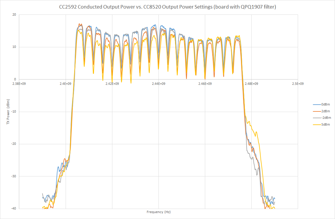
    I made a graph of the output power per channel often going up if I turn down the programmed output power of the CC8520.  I thought you may find this interesting.

  • Strange.
    - Is it any difference if you are doing the same without the filter?
    - Is it any change in the spectrum with and without the filter?
    - If you do some load pull measurements at an external lab, please do it with and without the filter.
  • Any news/ progress on this?
  • Hi TER,

    Sorry I thought I posted this plot yesterday but I guess it didn't go through.

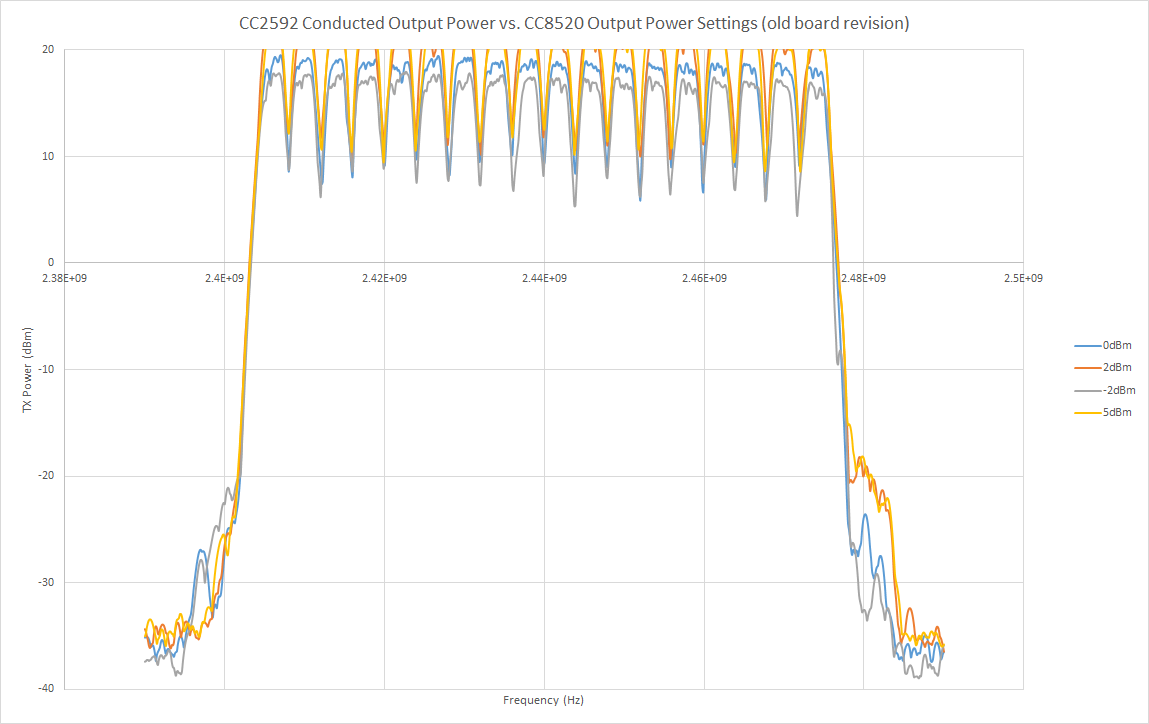
    Without the filter on the old board I see sort of the expected behavior when turning power down, see below:

    Thanks,

    Arthur

  • All measurements indicate that the filter for some reason causes problems. Have you been able to do load pull so far?
  • No, still no ability to do load pull yet.
  • I believe we need those results before being able to answer why you get the results you get.