This thread has been locked.

If you have a related question, please click the "Ask a related question" button in the top right corner. The newly created question will be automatically linked to this question.

BTPSVend and HCI over UART examples?

Hello,

I'm looking for example source code that utilizes the functionality within BTPSVend.c as well has some example source to read/write HCI command/events directly over UART.  I would like to utilize the HCI header files already provided by the SDK.

Thank you,

Satyajit

  • Hi Satyajit,

    There are many examples from the SDK itself that uses those APIs.
    The API you should be using is "HCI_Send_Raw_Command".

    Please let me know if you need any further information.

    Regards,
    Gigi Joseph.
  • Thanks for the response.

    I'm looking at the SPPDemo source but do not see when/where and how the HCI_VS_InitializeAfterHCIReset function is called or referred to except that it is somwhere within the BSC_Initialize function. I also looked for the HCI_Send_Raw_Command implementation but could not find it. How do these function call underlying UART functionality in HCITRAN? I'm trying to find the linkage or trace from SDK/API down to the UART driver/functionality.

    Again thanks,

    Satyajit
  • Hi Satyajit,

    The source to either is not provided.
    You can use the HCI_Send_Raw_Command() API directly to send/receive command/events over the UART. I don't understand why you need to source code for that.

    Regards,
    Gigi Joseph.
  • Hello,

    Let me back up a bit.  I don't necessarily need the source code or implementation for the HCI_Send_Raw_Command.  I've been using the SDK with the MSP-EXPF5438 kit and everything work good (running the SPP demo).   Now I'm porting this over into our product design which uses the MSPF6779A.  I wanted to do a quick batch of configuration tests of the UART by send a few HCI command and receiving some HCI Events.  To do so, I am trying to re-use as much of the SDK (HAL, HCITran, etc) as possible but not get bogged down by rest of the machinery.  So I thought, I could implement the HCI_VS_InitializeAfterHCIReset functionality in BTPSVend and VS_Set_Max_Output_Power functionality as a test.  So, to do this, I was trying to link/trace how the HAL, HCITran, BTVS and BTPSVend module interact.  How does HCI_Send_Raw_Command know which UART is configured on my MCU for example?  When do I call the HCI_VS_InitializeAfterHCIReset functionality to download the patch?

    On a completely unrelated topic...

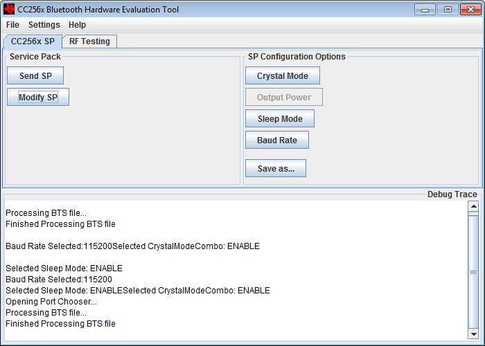
    I download the BTS (initscripts-TIInit_6.7.16_bt_spec_4.1.bts) and loaded it into the BHEL software.  I'm trying to Modify SP to enable Output Power functionality so I can use the VS_Set_Max_Output_Power in BTVS module.  I see this (see screenshot), the Output Power button is disabled.

    Thanks,

    Satyajit

  • Hi Satyajit,

    [Q] How does HCI_Send_Raw_Command know which UART is configured on my MCU for example?
    [A] The stack uses the handle from HCITR_COMOpen()

    [Q] When do I call the HCI_VS_InitializeAfterHCIReset functionality to download the patch?
    [A] This is called from within the BSC_Initialize(). From a device perspective, you can call it ~100ms after setting BT_EN high.
    The BSC_Initialize():

    1. Initializes the stack
    2. Calls HCI_VS_InitializeBeforeHCIOpen(),
    3. Opens the COM port - HCITR_COMOpen() gets called
    4. Calls HCI_VS_InitializeAfterHCIOpen()
    5. Calls HCI_VS_InitializeBeforeHCIReset()
    6. Calls HCI_VS_InitializeAfterHCIReset() - Firmware gets downloaded

    Regards,
    Gigi Joseph.
  • Thank you so much. This helps.

    The VS_Set_Max_Output_Power should work after the patch download? Or are there any further steps required? Also, can this function be called on-demand? That is do I need to set the power level, then reset the device or will it set it immediately?

    Again, Thanks,

    Satyajit
  • Hi Satyajit,

    It will set immediately, but you must call it immediately after downloading the firmware

    Regards,
    Gigi Joseph.
  • Hello,

    I'm trying to execute the HCI_Read_Transmit_Power_Level function prior to the VS_Set_Max_Output_Power. Both CURRENT and MAXIMUM return with StatusResult of 0x02 which is HCI_ERROR_CODE_NO_CONNECTION. I'm doing this within the OpenStack() sequence. Do have to set the Connectable mode prior to executing this sequence?
  • Hi,

    The "HCI_Read_Transmit_Power_Level " is a BT spec command. Please check the spec for more details -

    ***
    This command reads the values for the Transmit_Power_Level parameter for the specified Connection_Handle. The Connection_Handle shall be a Connection_Handle for an ACL connection.
    ***

    So you need to have an ACL connection to run this command.

    Regards,
    Gigi Joseph.
  • Thanks,

    I was able to execute HCI_Read_Transmit_Power_Level properly.

    I'm still confused about the VS_Set_Max_Output_Power.  Does this set the current TX Power or the max limit allowed?  Are there additional functions that set the current tx power value?

    I'm added two commands, GetTxPower and SetTxPower over the UART.  

    GetTxPower calls the HCI_Read_Transmit_Power_Level and SetTxPower calls the VS_Set_Max_Output_Power. SRes is the StatusResult.

    After I have connected (SPP demo), I execute the following

    Server>gettxpower
    Device SRes and current TX power: 0 and 12
    Device SRes and Max TX power: 0 and 12

    Server>settxpower 1
    Device SRes and current TX power: 0 and 1
    Device SRes and Max TX power: 0 and 1

    Server>settxpower 12
    Device SRes and current TX power: 0 and 12
    Device SRes and Max TX power: 0 and 12

    Yet... I don't see a change in the power consumption. I'm measuring board current using J2 VBAT_CC and R10.  Am I missing something? I would have expected there to be a relationship (drop) is consumption then I lowered the output power.

    Also, reading through the VS_Set_Max_Output_Power implementation, I cannot understand how it correlates to the Vector table in 

    http://processors.wiki.ti.com/index.php/CC256x_VS_HCI_Commands#HCI_VS_DRPb_Set_Power_Vector_.280xFD82.29

    the power level index range is 0 to 15 yet this function only accepts 0 to 12.

    Again thanks,

    Satyajit

  • Hi Satyajit,

    VS_Set_Max_Output_Power() sets the max output power - to correlate it with the DRPb_Set_Power_Vector, it sets the power level 15 to the value you are passing to the function, and sets the appropriate value for each of the levels following the rules mentioned in the wiki. It will also send the mandatory RF calibration command at the end.

    But as I mentioned earlier, it must be sent immediately after downloading the firmware. Please see: e2e.ti.com/.../1635058

    Regards,
    Gigi Joseph
  • Hello,

    So help me understand this a little more.  The VS_Set_Max_Output_Power function accepts values from 0 to 12.  The function runs for each modulation type followed by the internal calibration.  

    So if I call the function as follows 

    VS_Set_Max_Output_Power(BluetoothStackID, 0);

    power level 15 (12 dBm) is set to index 0, then calculates the rest of the values [1..12] ?

    VS_Set_Max_Output_Power(BluetoothStackID, 12);

    power level 15 (12 dBm) is set to index 12, the calculates the rest of the values[0..11] ?

    but the maximum i always 12 dBm?  How can I set it to a lower value?

    For my application, I wish to limit the range of the device link.  I wish to limit the range for the discovery (adverstising) state and also the connected state. Ranges need to be less than the max (12 dBm) .  So as an example.  When the device powers up and is discoverable, I want the max tx power to be say -23 dBm (requiring a certain proximity) but after it is paired with and connected to (active link), the max power is raised to -13 dBm to allowing for greater range.  Is this possible using VS_Set_Max_Output_power function or do I need other functionality?

    Thanks,

    Satyajit

  • Satyajit,

    "VS_Set_Max_Output_Power(BluetoothStackID, 12);
    power level 15 (12 dBm) is set to index 12, the calculates the rest of the values[0..11] ?"

    What is index here? What happens with the below code is that, the power level 15 is set to 12dBm, 14 to 7, 13 to 2 and so on.... Power level 1 is used for BLE (12 dBm with the above call).

    The BLE power cannot be changed dynamically or on the fly. It is set during initialization and should not be changed later on.

    Regards,
    Gigi Joseph.
  • Hello,

    I'm not using BLE, just Classic BDR/EDR.  Looking at the implementation of VS_Set_Max_Output_Power, it has two input parameters, the Stack ID and a MaxPower.

    Here are excerpts from the source code.

    /* * NOTE * The maximum output power is specified from 0 to 12 and */
    /* it specifies 4 dBm steps.

    ...

    /* Before continuing, make sure the input parameters appear to be */
    /* semi-valid. */
    if((BluetoothStackID) && (MaxPower >= 0) && (MaxPower <= 12))
    {

    ...

    }
    else
        ret_val = BTPS_ERROR_INVALID_PARAMETER;

    The above code, limits MaxPower to 0..12, also, MaxPower is a Byte so no values less than zero can be passed into it.  This is what is confusing me.  Looking at the CommandBuffer, here is what I think is happening.

    I called the function with MaxPower = 0

    for Index = 0 (GFSK)

    CommandBuffer = 0x00, 0x9C, 0x00, 0xD8, 0xD8, 0xD8, 0xD8, 0xD8, 0xD8, 0xD8, 0xD8, 0xD8, 0xD8, 0xE2, 0xEC, 0xF6, 0x00, 0xFF, 0x00, 0x00

    for index = 1 and 2 (EDR2 and EDR3)

    CommandBuffer = 0x00, 0x9C, 0xD8, 0xD8, 0xD8, 0xD8, 0xD8, 0xD8, 0xD8, 0xD8, 0xD8, 0xD8, 0xD8, 0xE2, 0xEC, 0xF6, 0x00, 0xFF, 0x00, 0x00

    where, 2x the output power per vector description

    0x9C = -100 (-50 dBm)
    0xD8 = -40 (-20 dBm)
    0xE2 = -30 (-15 dBm)
    0xEC = -20 (-10 dBm)
    0xF6 = -10 (-5 dBm)
    0x00 = 0 (0 dBm)

    1). This means the maximum power is set to 0 dBm? with 5 dBm step down to -20 dBm? not counting -50 dBm as part of the step.

    2). if #1 is correct, how do I select one of the other other steps? That is, I set max power to be 0 dBm but want the currently transmitted power level to be one of the lesser steps, say -15 dBm. Is there a different function for this?

    Thank you,

    Satyajit

  • Satyajit,

    2). if #1 is correct, how do I select one of the other other steps? That is, I set max power to be 0 dBm but want the currently transmitted power level to be one of the lesser steps, say -15 dBm. Is there a different function for this?

    >>> the device reduces/increases its power by one step on every LMP_incr_power_req or LMP_decr_power_req received. Please check the BT spec for more details.

    Regards,
    Gigi Joseph.
  • Hello,

    Thanks for your help.

    I will look into the LMP functionality.  So after all this, I'm still not able to detect if the VS_Set_Max_Output_Power is working properly.  Similar to the other forum thread (Please see: e2e.ti.com/.../1635058)  I'm calling this function immediately after the BSC_Initialize and there is a valid BluetoothStackID.  See below,

    /* Initialize the Stack */
    Result = BSC_Initialize(HCI_DriverInformation, 0);

    /* Next, check the return value of the initialization to see if*/
    /* it was successful. */
    if(Result > 0)
    {
    /* The Stack was initialized successfully, inform the user */
    /* and set the return value of the initialization function */
    /* to the Bluetooth Stack ID. */
    BluetoothStackID = Result;


    if (!VS_Set_Max_Output_Power(BluetoothStackID, 0))
    {
    ...// it always return as a success (Return = 0)
    }

    I am using the CC256xQFN-EM REV 1.2 daugherboard with the MSP-EXP430F5438.  The daugtherboard has the CC2564B chipset, so have enabled the __SUPPORT_CC256XB_PATCH__ and also downloaded the initscripts-TIInit_6.7.16_bt_spec_4.1.bts and converted it to CC256XB.h which used in BTPSVEND.c

    I have the daugtherboard modified per wiki to measure the V_BAT across R10.  Yet, even after modifying the Max Power, the board current measurement across R10 does not change.  I see the advert packet every 1.28 s and expect it's current consumption as measured across R10 to be less for lower values of max power.  So far it remains a constant, matter that power level I set.  Any suggestions?

    Thanks,

    Satyajit