This thread has been locked.

If you have a related question, please click the "Ask a related question" button in the top right corner. The newly created question will be automatically linked to this question.

CC2640R2F: Measuring Core Current Consumption.

Part Number: CC2640R2F
Other Parts Discussed in Thread: CC-DEVPACK-DEBUG

Hi,

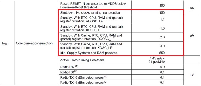
    I am trying to measure core current consumption based from the table below from datasheet. Our program goes into "Test Mode", where no profiles are initialized and then I turn off all leds, buzzer, and accelerometer. But, I am measuring 16 mA. The current consumption goes higher if I turn on any peripherals. Our product uses 32.768 KHz XOSC_LF and 24 MHz XOSC_HF crystals.

How do I setup my CC2640R2F based product in order to measure 1.3 uA or 3 uA?

- kel

  • Hi Markel,

    Have you closed the external flash? Please see the Measuring Bluetooth Low Energy Power Consumption application report: http://www.ti.com/lit/swra478
  • Marie H said:
    Have you closed the external flash?

    We do not have external flash connected because the CC2640R2F is configured for On-Chip OAD. Do, I still need to close external flash?

    At our Test Mode repeated UART read callback is running, so that may contribute to current consumption. 

    - kel

  • Hi Kel,

    You still need to close the external flash.
  • Hi Marie H,

    If I run PinStandby example program at CC2640R2 Launchpad with all jumpers removed, how much current would I be able to measure? From the table in the red box, would I be expecting to measure 1.3 uA?

    - kel
  • Hi Marie H,

    I am using 5XD board files. I added ExtFlash.c and ExtFlash.h then I got these errors below. Do I still need to close External Flash since these pins are not initialized on boot up? If I still need to close External Flash, then I would need to copy from other board files how these pins are initialized?

    identifier "Board_SPI_FLASH_CS" is undefined
    identifier "Board_FLASH_CS_ON" is undefined
    identifier "Board_FLASH_CS_OFF" is undefined

    - kel
  • Hi Kel,

    Are you measuring on your own HW or the LaunchPad?

    On the LaunchPad you need to use the LaunchPad board files and close the flash as Marie says. With all jumpers removed the Standby current consumption should be around 1.3 uA.

    On your custom HW there is no need to do anything related to external flash if you do not have that on your board. You must of course ensure that all IOs are configured to a state where they do not draw current, and also put all other external active circuitry in low power mode.

    Regards,
    Fredrik
  • Hi Fredrik K,

       Thanks for your reply.

       At the pinStandby example program for the CC2640R2 Launchpad, we were able to measure in the uA range value.

       For our CC2640R2F 5XD base product, the reason why we are getting 16mA, because it is connected to RS232 board and CC-DEVPACK-DEBUG board. After removing both board connections we are getting 2 mA current measurement.

    Our IO ports pin properties are below.

        /* LED IO configuration */
        IO_LED_RED   | PIN_GPIO_OUTPUT_EN | PIN_GPIO_LOW | PIN_PUSHPULL | PIN_DRVSTR_MAX,       /* LED initially off */
        IO_LED_GREEN | PIN_GPIO_OUTPUT_EN | PIN_GPIO_LOW | PIN_PUSHPULL | PIN_DRVSTR_MAX,       /* LED initially off */
        /* Buzzer IO configuration */
        IO_BUZZER_EN_1     | PIN_GPIO_OUTPUT_EN | PIN_GPIO_LOW | PIN_PUSHPULL | PIN_DRVSTR_MIN,      /* Init for EN1 (Buzzer) */
        IO_BUZZER_EN_2     | PIN_GPIO_OUTPUT_EN | PIN_GPIO_LOW | PIN_PUSHPULL | PIN_DRVSTR_MIN,      /* Init for EN2 (Buzzer) */
        IO_BUZZER_PWM_DIN  | PIN_GPIO_OUTPUT_EN | PIN_GPIO_LOW | PIN_PUSHPULL | PIN_DRVSTR_MAX,      /* Init for Buzer data In IO_BUZZER_PWM_DIN (Buzzer) */
        IO_BUZZER_POWER    | PIN_GPIO_OUTPUT_EN | PIN_GPIO_HIGH| PIN_PUSHPULL | PIN_DRVSTR_MIN, 
        /* Button IO configuration */
        IO_BUTTON_MFB | PIN_INPUT_EN | PIN_PULLUP | PIN_IRQ_NEGEDGE | PIN_HYSTERESIS,    
        ACC_INT    | PIN_INPUT_EN | PIN_PULLDOWN | PIN_IRQ_DIS | PIN_HYSTERESIS,
        ACC_POWER  | PIN_GPIO_OUTPUT_EN | PIN_GPIO_HIGH | PIN_PUSHPULL | PIN_DRVSTR_MIN,
        /* Test Mode configuration */
        IO_TEST_MODE  | PIN_INPUT_EN | PIN_PULLUP,
        PIN_TERMINATE

    Our TX Power is set to 4 DBM

     HCI_EXT_SetTxPowerCmd(HCI_EXT_TX_POWER_4_DBM);  /*set tx power to 4 DBM */
      HCI_EXT_SetRxGainCmd(HCI_EXT_RX_GAIN_HIGH); /* enable high gain mode */

    Our default advertising interval is set to 100 ms

    // Advertising interval when device is discoverable (units of 625us, 160=100ms)
    #define DEFAULT_ADVERTISING_INTERVAL          160

    We are measuring 2 mA using Digital Multimeter, and it seem constant. The current goes up to 4 mA when I activate the buzzer using Immediate Alert. With our advertising interval set to 100 ms, we should be able to see the current go down, but we are getting constant 2 mA. Our hardware guy says 2 mA is not okay for our battery powered product.

    How can I achieve standby current measurement in uA?

    - kel

  • Hi Fredrik K,

    I set POWER_SAVING predefined symbol and now we are getting current measurement in the uA range. But we are not able to get a steady uA reading using our Digital Multimeter because of our advertising interval.

    - kel
  • Hi,

    In addition to this I am doing a feature where we type a command at Tera Term. and then will go to C function that will force the CC2640R2F into Standby Mode. This so we can measure the Standby Current. This feature is for our Test Group.

    I found this document www.ti.com/.../sprui20.pdf and there is a code to enter Standby Mode under "Power Standby Policy". Would this code work for CC2640R2F without changes?

    - kel
  • Hi Kel,

    We don't recommend using Power_sleep() as this function does not check declared constraints.

    You can use sleep(), please see the empty example project for implementation.
  • Hi Marie H,

    At the sample code at sprui20, it seems to check the constraints before going to sleep.

    I tried the Pin Standby Example Program and I was not able to read Standby Current of 1.5 - 1.3 uA using or Fluke Digital Multi-Meter.

    I configured the simple peripheral to periodic event to happen one time only and then call DELAY_MS(30000). The DELAY_MS calls Task_sleep(). I measured Standby Current in mA and not uA.

    I am doing this feature for our Production and Test Group. We have a testing setup that is connected to UART. If I type a command for sleep current test, the code should force application to go to Standby Mode, so we can measure the Standby Current as mentioned in the datasheet.

    I have not tried yet the sample code at sprui20. Hopefully it works.

    - kel