This thread has been locked.

If you have a related question, please click the "Ask a related question" button in the top right corner. The newly created question will be automatically linked to this question.

RTOS/CC2650STK: Add UART driver to a CC2640 project

Part Number: CC2650STK
Other Parts Discussed in Thread: CC2640,

Tool/software: TI-RTOS

Hi all, 

I am trying to do a project on CC2640 with BLE SDK 2.02, but for some reasons, I will disable the BLE features on such a BLE processor.

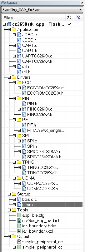
So I make a new project like this. (modified from the simple_peripheral project of CC2650STK)

Also, I modified the main function as 

int main()
{
  PIN_init(BoardGpioInitTable);

  Power_setConstraint(PowerCC26XX_SB_DISALLOW);
  Power_setConstraint(PowerCC26XX_IDLE_PD_DISALLOW);

  /* Initialize ICall module */
  //ICall_init();

  JDBGInit();
  
  BIOS_start();     /* enable interrupts and start SYS/BIOS */
  
  return 0;
}

I guess this must be the easiest project. 

The JDBGInit() is the UART Init function. If the UART Init successfully, the UART will print a character 'a' with \r\n. 

Here is the JDBGInit(): 

void JDBGInit(){
    UART_init();
    UART_Params_init(&JDBGParams); 
    JDBGParams.baudRate = 115200;
    JDBGHandle = UART_open(CC2650STK_UART0, &JDBGParams); 
    if (JDBGHandle)
        UART_write(JDBGHandle, "a\r\n", 3);
}

After building this simple_peripheral project, and flashing my image through smartRF flash programmer 2, my CC2640 never put any character on screen. 

What is weird is that I did the same thing on sensortag project (the same pin table, the same main function), the character is printed well.

By the way, I modified the pin table in C:\ti\simplelink\ble_sdk_2_02_01_18\src\boards\CC2650STK\CC2650STK.h as 

#define Board_DP4_UARTRX            IOID_2
#define Board_DP5_UARTTX            IOID_3
#define Board_RELAY                 PIN_UNASSIGNED
#define Board_AUDIO_DI              PIN_UNASSIGNED

Do anyone know what is the problem in this modification?

I think it's a very easy initialization project for our application, but after 3 days tracing...I still have no idea what is the difference between these 2 projects.

(I set all the same project options in IAR but in vain)

  • Hi Jammy,

    In addition to the changes that you made in the pin table in CC2650STK.h, did you make the necessary changes in the BoardGpioInitTable found in CC2650STK.c?

    -Sy Su
  • Hi Sy. Thanks for your reply.

    I didn't make any changes for BoardGpioInitTable.

    Do you mean I should comment out these lines?

    Board_RELAY      | PIN_INPUT_EN | PIN_PULLDOWN | PIN_IRQ_BOTHEDGES | PIN_HYSTERESIS,      /* Relay is active high          */
    Board_MPU_INT    | PIN_INPUT_EN | PIN_PULLDOWN | PIN_IRQ_NEGEDGE | PIN_HYSTERESIS,        /* MPU_INT is active low         */

    Or you mean the driver part should be changed?

    /*
     *  ============================= UART begin ===================================
     */
    #if defined(__TI_COMPILER_VERSION__)
    #pragma DATA_SECTION(UART_config, ".const:UART_config")
    #pragma DATA_SECTION(uartCC26XXHWAttrs, ".const:uartCC26XXHWAttrs")
    #endif
    
    /* Include drivers */
    #include <ti/drivers/UART.h>
    #include <ti/drivers/uart/UARTCC26XX.h>
    
    /* UART objects */
    UARTCC26XX_Object uartCC26XXObjects[CC2650STK_UARTCOUNT];
    
    /* UART hardware parameter structure, also used to assign UART pins */
    //const UARTCC26XX_HWAttrsV1 uartCC26XXHWAttrs[CC2650STK_UARTCOUNT] = {
    const UARTCC26XX_HWAttrs uartCC26XXHWAttrs[CC2650STK_UARTCOUNT] = {
        {
            .baseAddr       = UART0_BASE,
            .powerMngrId    = PERIPH_UART0,//PowerCC26XX_PERIPH_UART0,
            .intNum         = INT_UART0, //INT_UART0_COMB,
            //.intPriority    = ~0,
            //.swiPriority    = 0,
            .txPin          = Board_UART_TX,
            .rxPin          = Board_UART_RX,
            .ctsPin         = PIN_UNASSIGNED,
            .rtsPin         = PIN_UNASSIGNED
        }
    };
    
    /* UART configuration structure */
    const UART_Config UART_config[] = {
        {
            .fxnTablePtr = &UARTCC26XX_fxnTable,
            .object      = &uartCC26XXObjects[0],
            .hwAttrs     = &uartCC26XXHWAttrs[0]
        },
        {NULL, NULL, NULL}
    };
    /*
     *  ============================= UART end =====================================
     */

    I guessed they are should be the same because I only changed the pin assignment.

    Could you help give me some suggestion? Thanks! 

  • Hey Jammy,

    Those changes look fine to me.

    You shouldn't have to comment out those lines since you have defined both of those as PIN_UNASSIGNED.

    You still have these lines in the BoardGpioInitTable correct?

    Board_UART_RX | PIN_INPUT_EN | PIN_PULLDOWN,                                            
    
    Board_UART_TX | PIN_GPIO_OUTPUT_EN | PIN_GPIO_HIGH | PIN_PUSHPULL,

    When you call UART_Open does JDBGHandle return as a valid handle? In other words, if you modify the code to the following does the project get into the while loop?

    if (JDBGHandle)
    
           UART_write(JDBGHandle, "a\r\n", 3);
    
    else
    
           while(1);

    -Sy Su

  • Thanks for your reply!
    Yes I didn't change anything for Board_UART_RX and Board_UART_TX.
    And I have checked the output of the snippet you above.
    In my debugger, I can find the JDBGHandle is not void. But there are still no outputs.

    Another thing is I found a difference between these 2 project(sensortag vs simple_peripheral):
    When I was building the sensortag project, I used the FlashROM configuration. (The image can print characters.)
    But the configuration I used for simple_peripheral was the FlashROMOnly_OAD_ExtFlash. (The image can not print characters.)
    Meanwhile, I was trying to build sensortag with FlashOnly_OAD. (The image can not print characters.)

    I thought I shouldn't flash an OAD/Extflash image with SmartRF Programmer 2, right?
    After I moved my project to Sensortag of FlashROM, it seems OK to me. I can build my application with debug UART now.
    Please comment if you have any idea about image difference.
    I am not sure why I can not use the image of OAD/ExtFlash with SmartRF Programmer.
    I know OAD is for over-air-download, and Extflash is for external flash. But I have no idea about the differences of these images.

    Thanks very much!
  • Hi Jammy,

    Glad to hear that you got it working.

    For the OAD version of the project, were you building and flashing the stack first then building and flashing the app second?
    When you do this, you want to make sure in Flash Programmer 2 that the "Pages in image" option is selected to avoid the stack and app image from overwriting each other.

    In the SDK there is also a document called "CC2640 BLE OAD User's Guide". This is located in C:\ti\simplelink\ble_sdk_2_02_01_18\docs
    If you can't locate it, it is also available here: e2e.ti.com/.../CC2640-BLE-OAD-User_2700_s-Guide.pdf

    Section 8.2 details how to run the OAD configuration of the project correctly and Section 7.1 provides insight on OAD. When you see OAD ExtFlash, that is another name for Off-chip OAD.

    -Sy Su