This thread has been locked.

If you have a related question, please click the "Ask a related question" button in the top right corner. The newly created question will be automatically linked to this question.

RTOS/CC2640R2F: Multiple Connection throughput problem

Part Number: CC2640R2F
Other Parts Discussed in Thread: CC2540

Tool/software: TI-RTOS

Hi!

Working with Texas Instrument CC2640R2F Simple link Bluetooth low energy wireless MCU that is running a modified version of the SPP_BLE client/server example code.
Using the blestack (BLE 4.2) and Simple link CC2640R2 SDK version 1.40.00.45.

My focus is questions regarding why we can’t get even close to the normal PHY 1 Mbit/s transfer speed as the total roundtrip time is too high due to

Our current setup consists of one (1) Central and four (4) Peripherals running the following parameter settings:

Each transfer consists of one 10-byte request C→P and one 80 – 1030-byte response P→C.

Each transfer is sent to all peripherals every 200 ms.
All tests always send 100 transfers.

Tests are maximum payload settings achieved using a normal PDU 27 and Connection Interval of 26.5 ms with 1 and 4 peripheral setup.
Below are the maximum possible settings we can use until we start getting peripheral pending issues due to scheduling latency and transfers not completing fast enough.

Parameters

Test 1 P

Test 4 P

Number of peripheral:

1

4

Max number of PDU:

30

30

Max PDU size:

27

27

MTU size:

23

23

Packet payload size:

20

20

Total payload size:

530

80

Number of packets per interval:

27

4

Total number of transfers:

100

100

Total number of packets:

2650

400

Min connection interval:

26.5 ms

26.5 ms

Max connection interval:

26.5 ms

26.5 ms


Results running with Connection Interval 26.5 ms:


Test 1 P

Test 4 P

Number of successful packets:

100

100

Number of CRC error packets:

0

0

Average roundtrip C↔P:

124 ms

178-220 ms

Min roundtrip C↔P:

108 ms

156-172 ms

Max roundtrip C↔P:

141 ms

188-235 ms


As soon as the roundtrip time start to get higher than 200 ms we start to see issues.
So, I believe that due to the low overall throughput, PDU’s piles up in the system buffers and we start to see pending issues and in the end, nothing comes through...


Problems we are facing:


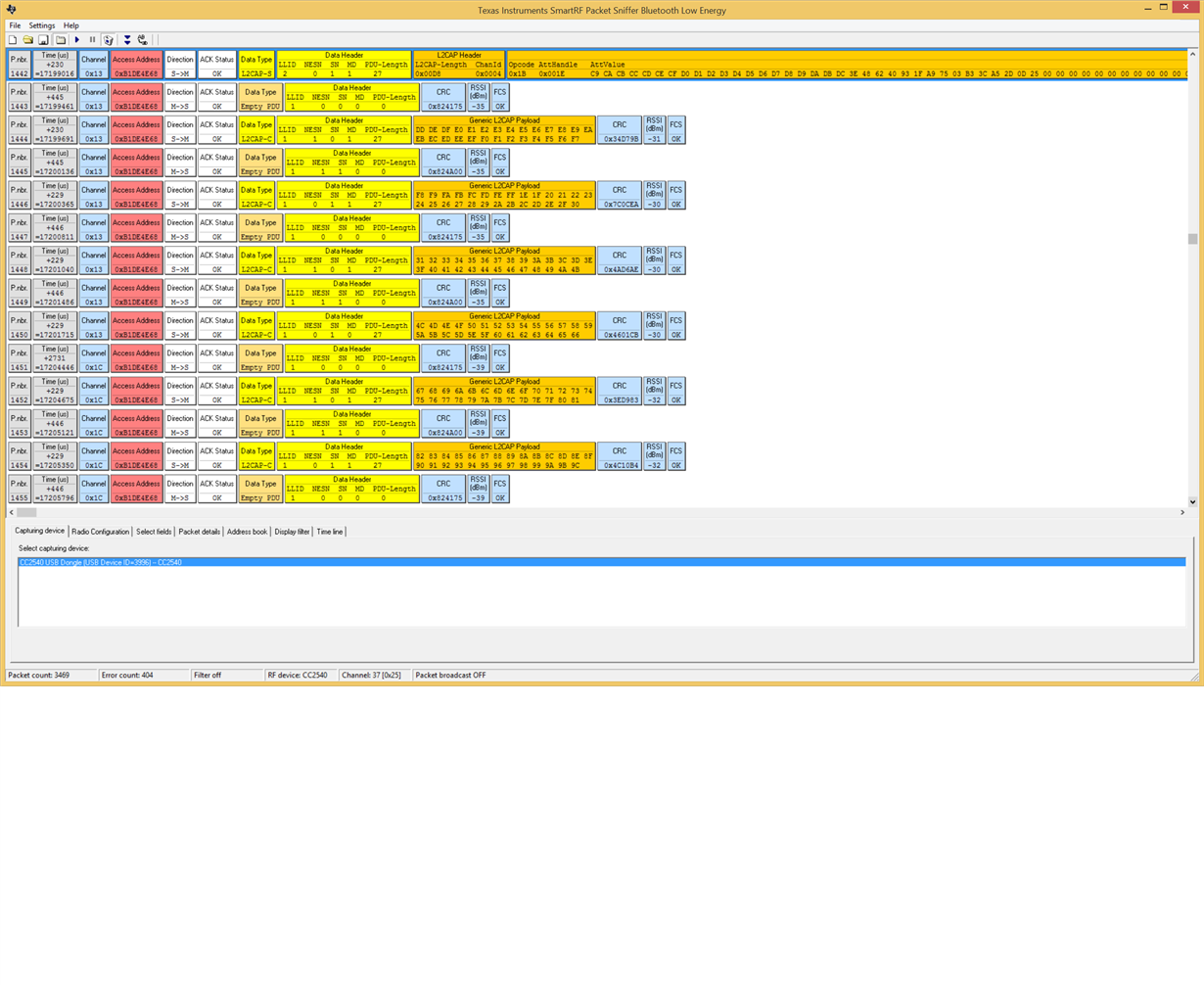
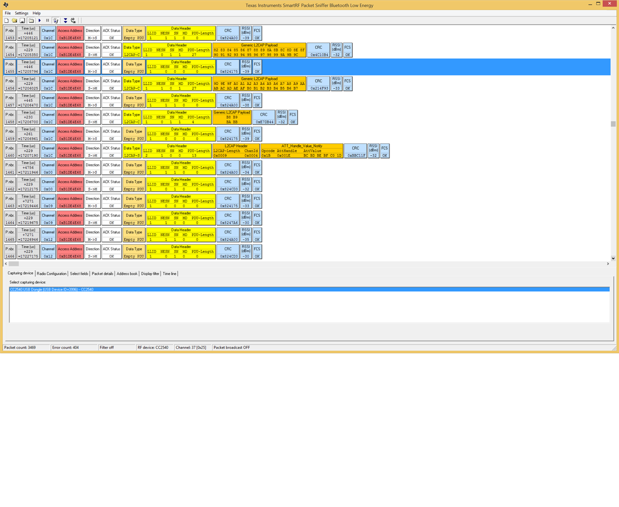
  1. When using a BLE sniffer we notice that during the connection event (P → C) the connection interval is not filled to its limits, why?
    We would like to see the CC2640R2F fill the air with as many payload packets as possible within the boundaries of the connection interval settings.


  1. Higher connection interval setting lowers the number of possible PDU transferred within the given connection interval timeframe, why?
    For example: changing a working setting from 26.5 ms to 100 ms connection interval with a data payload of 530 bytes works when using 26.5 ms (100% packets transferred)
    To transfer all packets using 100 ms connection interval the data payload needs to be lowered to 40 bytes.


  1. How are multiple peripheral connection events scheduled? In sequence order: C→P1, P1→C  C→P2, P2→C  C→P3, P3→C  C→P4, P4→C or something similar as I’m guessing that it requires at least two connection interval (one in each direction) times number of peripherals?


  1. To be able to connect to all four peripherals we need to set max/min connection interval as high as 32.5 ms otherwise all peripherals are not discovered by central.
    How much of the airtime can be accounted for when discovery is started? Is the formula for the connection interval 12.5 ms + (5 ms * number of peripherals) valid to assume?
  2. Are there any radio “interdependence of” parameter calculation tool or image explaining the executed scheduling scheme?
    Anything that makes it easier to understand and optimize parameter settings.

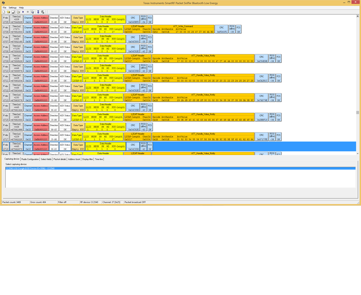
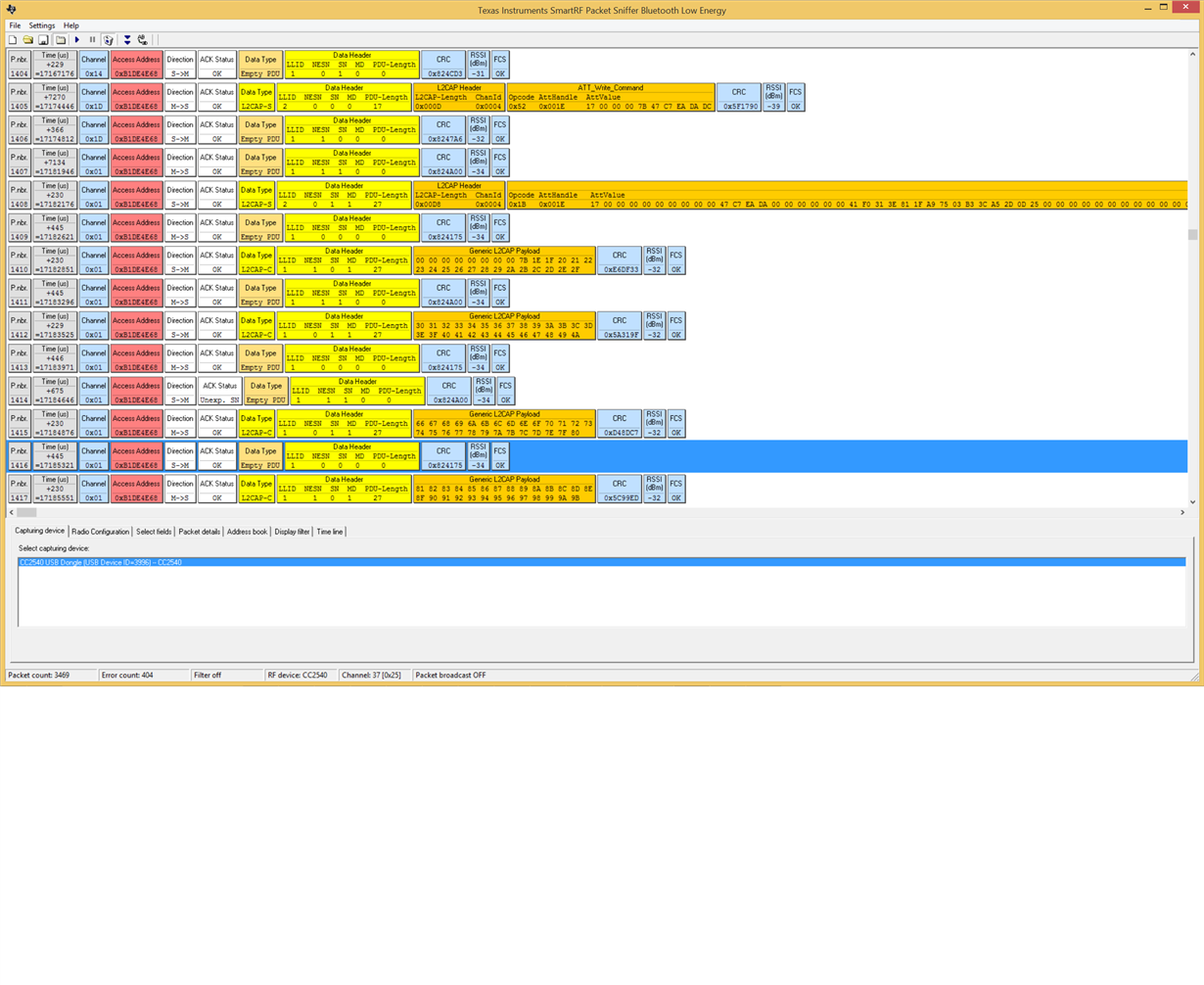
A different test we did was to change the PDU size. For this test we used a CC2540 USB Dongle using SmartRF sniffer

In this setting we are using a connection interval of 7.5 ms and PDU of 27 and the notification is adding enough data to fill 11 PDUs.

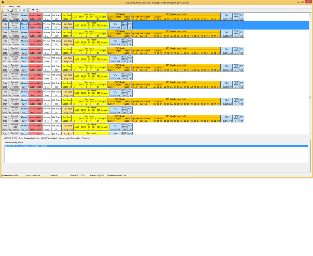
We see the PDU going out with a SmartRF sniffer. The following connection interval the peripheral device responds with x PDUs and not the expected 11 PDUs (660us*11 == 7260 us) that should fit within a connection interval of 7.5 ms. Note that after the next anchor point the remaining PDUs is sent. Note that all data is successfully received at central.

What might the reason be that the CC2640R2F choose to send only 7 PDUs and not 11 as the Bluetooth specification suggest should be done?

Here is a SmartRF sniffing session of the ping and response. Notice the long silence at P. nbr. 4722

Then we change the PDU to 220:

In this setting we are using a connection interval of 7.5 ms and PDU of 220 and the notification is adding enough data to fill 3 PDUs.

We see the PDU going out with a CC2540 USB Dongle using SmartRF sniffer. The following connection interval the peripheral device responds with 2 PDUs (Size 220) and not the expected 3 PDUs that should fit within a connection interval of 7.5 ms. Following the next anchor point the remaining PDU is sent. Note that all data is successfully received at central.
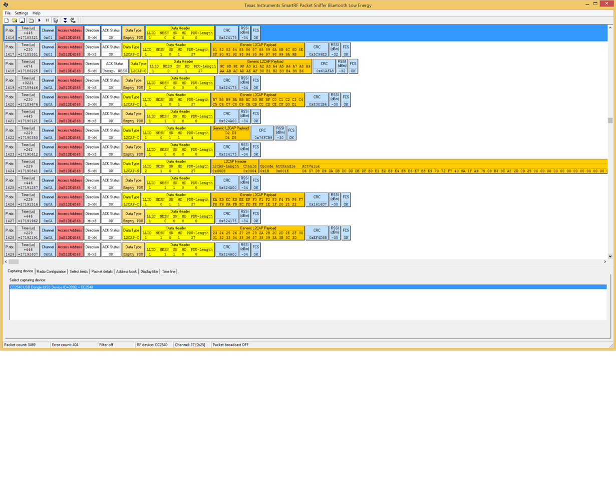
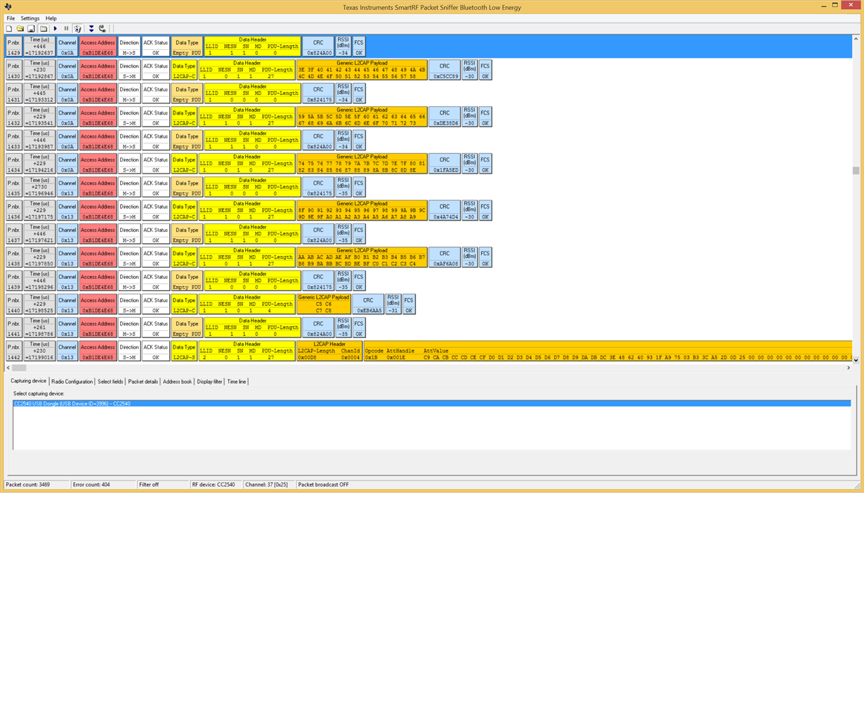
 

     What might the reason be that the CC2640R2F seems to send only 1 PDUs in each connection interval and not 3 as the Bluetooth specification suggest should be done? Our time measuring on our PC also confirms that 3 connection intervals is needed for the notification response instead of the expected 1.

A lot of questions in one post, but i hope to get som anwers to some of the them:)

  • Hi Tobias,

    Thanks for posting and providing lots of information, but before we dive super deep I would like to get a little bit of context: is there a reason that you have chosen the SPP example while trying to handle many connections at once? I want to make sure this is the right choice for your application as there could be other options that might be better suited.

    Additionally, I wanted to mention that 1Mbps is the modulation frequency, not the actual rate of usable application data. When you are discussing throughput, are you meaning actual application data throughput (not the data for the BLE protocol headers)? BLE protocol itself inherently has overhead for the protocol layers so not all bits actually carry your application data. You may want to see this: github.com/.../throughput_example.md That includes some data on best throughput you might be able to achieve with the 1Mbps PHY. You could improve this some with the 2Mbps high-speed PHY on BLE5, but there will still be overhead considerations for the protocol itself.

    Regards,
    Katie
  • Hi, Katie!

    Tanks for the response! The reason for chosen the SPP example is that we have a Serial port in both ends and the start of the project was to implement a 1 to 1 serial interface, this works great. but when the central was "upgraded" to handle 4 connections att the same time and still provide a serial port to all four, the problems begin. The throughput did not go the 1/4 as expected or a bitt less. When having 4 connections active then we have so low throughput we can not use this solution. But we have crosscheck many times with the multi_role example project to see if we have any understandable difference that could influenced the throughput in the way we are experiencing. When it comes to the throughput we do not expect to get 1Mbit/s, but we was at lest expecting 150kbit/s for every peripheral. Because the Throughput example deliver 780kbit/s to one connection. To show you a better picture of what we try to achieve.

    Hope this give you the background info you need to dive deeper into our problem.

    Thanks!

  • Hi Tobias,

    With multiple connected devices, there is typically only 1 frame from master and slave is allowed per peer device for scheduling reasons. This seems to match with your observations.

    With one connected device, there's memory (heap) limitations that you perhaps run into, as well as a fixed number of packet "slots" in the stack - configurable in ble_user_config.h :: MAX_NUM_PDU.

    1. When using a BLE sniffer we notice that during the connection event (P → C) the connection interval is not filled to its limits, why?
      We would like to see the CC2640R2F fill the air with as many payload packets as possible within the boundaries of the connection interval settings.

    I assume you are talking about with only one connected device here. If it's not filled to its limits, this is likely because the number of slots were exhausted and no new notifications were entered during the connection event to take up the slack, or because two consecutive frames had CRC errors.

    1. Higher connection interval setting lowers the number of possible PDU transferred within the given connection interval timeframe, why?
      For example: changing a working setting from 26.5 ms to 100 ms connection interval with a data payload of 530 bytes works when using 26.5 ms (100% packets transferred)
      To transfer all packets using 100 ms connection interval the data payload needs to be lowered to 40 bytes.

    That's not how it is supposed to go, but it could be that you run into heap limitations, or that the transmit queue slots are full. You can, if you wish, continuously try to call GATT_Notification during a connection event to re-up the transmit queue. This would be more challenging with more connected slaves because you can't really know which slave is currently active. On the other hand, the number of frames per multiple connected slave is limited to typically 1 in any event.

    1. How are multiple peripheral connection events scheduled? In sequence order: C→P1, P1→C  C→P2, P2→C  C→P3, P3→C  C→P4, P4→C or something similar as I’m guessing that it requires at least two connection interval (one in each direction) times number of peripherals?

    The connection events are scheduled as you suggest, but only one connection event per peripheral, as both the master and the slave can send at least one packet within a connection interval.

    1. To be able to connect to all four peripherals we need to set max/min connection interval as high as 32.5 ms otherwise all peripherals are not discovered by central.
      How much of the airtime can be accounted for when discovery is started? Is the formula for the connection interval 12.5 ms + (5 ms * number of peripherals) valid to assume?

    The scanning/initiating is a secondary operation which tries to use the time left over, or between, scheduled connection events. Some time is naturally needed for this, and that formula is at least a decent rule of thumb, but experimentation is the best guide.

    1. Are there any radio “interdependence of” parameter calculation tool or image explaining the executed scheduling scheme?
      Anything that makes it easier to understand and optimize parameter settings.

    Unfortunately not. This is something we are planning to provide, but for now the most detailed documentation is what you have seen in the multirole example.

    I have not tried myself with multiple connections, but potentially you could use the DataLength Extention feature of BT 4.2. Set the global MAX_PDU_SIZE to something, and also call the below to set the TX datalength, as seen in simple_peripheral.c,

      {
        //Set initial values to maximum, RX is set to max
        #define APP_SUGGESTED_PDU_SIZE 251 //default is 27 octets(TX)
        #define APP_SUGGESTED_TX_TIME 2120 //default is 328us(TX)
    
        // This API is documented in hci.h
        // See BLE5-Stack User's Guide for information on using this command:
        // software-dl.ti.com/.../data-length-extensions.html
        HCI_LE_WriteSuggestedDefaultDataLenCmd(APP_SUGGESTED_PDU_SIZE, APP_SUGGESTED_TX_TIME);
      }

    See also the documentation on DLE at http://dev.ti.com/tirex/content/simplelink_cc2640r2_sdk_1_50_00_58/docs/blestack/ble_user_guide/html/ble-stack-3.x/data-length-extensions.html

    Best regards,
    Aslak

  • Hi!

    We have already tried to change the settings of the PDU and TX time, whit minimum effect, but when looking in to HCI_LE_WriteSuggestedDefaultDataLenCmd I see that in the ble5 throughput example for CC2640R2

    https://github.com/ti-simplelink/ble_examples/blob/simplelink_sdk-1.40/examples/rtos/CC2640R2_LAUNCHXL/ble5apps/throughput_central/src/app/throughput_central.c

    The central does a HCI_LE_WriteSuggestedDefaultDataLenCmd(*txOctets, txTime); with txTime set to 17040 us when PDU is 251

    According to documentation on DLE.

    http://dev.ti.com/tirex/content/simplelink_cc2640r2_sdk_1_40_00_45/docs/ble5stack/ble_user_guide/html/ble-stack-5.x/data-length-extensions.html?highlight=hci_le_writesuggesteddefaultdatalencmd#null

    Time “The maximum number of microseconds that the device takes to transmit or receive a PDU at the PHY rate. This parameter uses units of microseconds (us). “

    And since a single PDU never can be greater then 251 bytes (2120 us at 1 Mbps PHY) what would an 8 times greater tx time do?

    Aslak N. said:
    1. When using a BLE sniffer we notice that during the connection event (P → C) the connection interval is not filled to its limits, why?
      We would like to see the CC2640R2F fill the air with as many payload packets as possible within the boundaries of the connection interval settings.

    I assume you are talking about with only one connected device here. If it's not filled to its limits, this is likely because the number of slots were exhausted and no new notifications were entered during the connection event to take up the slack, or because two consecutive frames had CRC errors.

    Yes correct it was only one connected device in this case. The number of slots was clearly not exhausted as seen in the second Smart RF sniffer picture where you can see a 3223 us halt in transmission before it is resumed. This happens every single time so it isn't a random problem. If I read the SPP_BLE server code right there is in the end only a single call to GATT_Notification() that transfers all our data. Is there any way to improve the performance of GATT_Notification()?

    I have seen that other vendors of BLE chips use Parallel handling of multiple slaves. To be exact the CI between the slaves is shifted 1/(#slaves). Is this something that is possible to enable in the cc2640r2 chip?

    Because our application require higher throughput from Peripheral to center. With the command HCI_EXT_SetMaxDataLenCmd it is possible to change the Tx and Rx time independent of each other? Do we need to the this in both the cental and peripheral?

    How does L2CAP_NUM_PSM and L2CAP_NUM_CO_CHANNELS defines correlate to the use of multi connections? The documentations regarding these defines are limited.

    In the BLE Stack User guide i found:

    "This is important to understand; both the transmit and receive buffers are allocated based on the respective PDU sizes negotiated for each connection. By default, there can be up to 8 TX buffers and 4 RX buffers active per connection at a given time. In the worst case scenario, this could mean about 3012 Bytes per connection of HEAP utilization with a PDU size of 251 Bytes."

    Is it correct when i calculate (4+8)*251 bytes => 1012. Why is the allocated size 3012?

    Is there a way to use the same RX buffers for all connections? because the stack only talk to one peripheral at the time/connection interval. I do not see the need of a RX buffer per connection, when the only one connection is active, att any given time.

    Thanks!

  • Hi Tobias,

    For the throughput example, this timing number is to accommodate for Coded PHY as well, which is 8 times slower. When both a byte and a time value is given in, the minimum of the two are used, bytes and time being corrected in the background for the active phy.

    In your second sniffer picture I can see 4 packets being sent in one connection event. Admittedly the default MAX_NUM_PDU is 5, but the slave needs to keep the last frame it sent for each connection interval because that isn't acked by the master until the first frame of the next connection interval. This is what I mean by slots.

    GATT_Notification will queue up one notification packet. That's all it does. It can return SUCCESS(0x00) or something else indicating either out of memory or out of slots. To increase the performance you would have to increase the MTU size and/or use BLE4.2 DataLenght Extension. You can also keep calling GATT_Notification in a loop (or with a short timer) so that you fill up slots from the application task while they are sent out over the air.

    We unfortunately do not automatically or manually support shifting the connected devices such that they get an equal amount of air-time.

    You can set the Tx and Rx time independently. Rx will by default (as long as both sides support BLE4.2 DLE) use the MAX_PDU_SIZE as its Rx window size. The HCI_LE_WriteSuggestedDefaultDataLenCmd command must also be called if you wish to increase the size of the transmit packets.

    L2CAP_NUM_PSM and L2CAP_NUM_CO_CHANNELS are not related to this at all. It's for L2CAP Connection Oriented Channels which will not help you in any way here.

    I suppose your calculation is the more correct one. Event that one is a bit off, because there is always some overhead included (which I'm not exactly sure but a few bytes).

    No you can not use the same RX buffer. In a way I suppose that would make sense though. But it is the way it is due to the layers being decoupled and may not have time to process slave 1 before slave 2 starts its connection event.

    Best regards,
    Aslak
  • Hi!

    Thanks for the explanation regarding the Tx times.

    Aslak N. said:
    In your second sniffer picture I can see 4 packets being sent in one connection event. Admittedly the default MAX_NUM_PDU is 5, but the slave needs to keep the last frame it sent for each connection interval because that isn't acked by the master until the first frame of the next connection interval. This is what I mean by slots.

    We are currently setting MAX_NUM_PDU to 30 so that should not be the issue here (If we use MAX_NUM_PDU 5 we get blePending since we then try to add data to fast for the blestack to handle). Are there any limitation to the number of PDUs or does the calling of GATT_Notification trigger something in the stack to continue after 5 PDUs?

    Aslak N. said:
    GATT_Notification will queue up one notification packet. That's all it does. It can return SUCCESS(0x00) or something else indicating either out of memory or out of slots. To increase the performance you would have to increase the MTU size and/or use BLE4.2 DataLenght Extension. You can also keep calling GATT_Notification in a loop (or with a short timer) so that you fill up slots from the application task while they are sent out over the air.

    We check the return values from GATT_Notification and we only get SUCCESS as long as we do not try to send to many PDUs (more then 30 then we get blePending or if we try to increase MAX_NUM_PDUS even higher we get a No Resource error).

    Is there a way to tell if what we trying to do something that is not possible to do? With our demand on roundtrip and throughput according the my second post in this thread? Are we on 100% what BLE can do or are we trying to get out 200% of this chip and stack?

    //Tobias

  • Hi Tobias,

    The only other limitation I can think of is heap, or other scheduled BLE activity. There's only 3 and 5 ms left in the connection events in picture #2, and so you wouldn't be able to send 30 here in any case.

    With one connection active you should, if you follow the throughput example approximately, reach the same speed as it does.

    But to your requirement on 150kbit/s per slave, I don't think you can reach this reliably since as mentioned the link layer does not shuffle the connections to give them space to utilize the available air-time.

    Best regards,
    Aslak
  • Hi!

    Aslak N. said:
    The only other limitation I can think of is heap, or other scheduled BLE activity. There's only 3 and 5 ms left in the connection events in picture #2, and so you wouldn't be able to send 30 here in any case.

    We do not expect to get all 30 in on CI, but we expect it to use the available time left of the CI. The3-5ms should at least accommodate for an 3-4 extra PDUs. Or are there a Back-of time before the next CI that the stack do not alow any traffic?

    //Tobias

  • Hi Tobias,

    There is some turnaround time before each new connection event, and so at some point it will be cut short even if more data is available to send, but I don't have it characterized, unfortunately.

    Best regards,
    Aslak